MDS-C1-SPA Series INSTRUCTION MANUALib1500152(eng)a.pdf - 第48页
2. Wiring and Connection 2 - 20 2-5-2 Connecting the grounding cable (1) Connecting the protective grounding (PE) and frame ground (FG) Each unit has a terminal or mounting hole to connect PE ( ) or FG. Please connect an…
2. Wiring and Connection
2 - 19
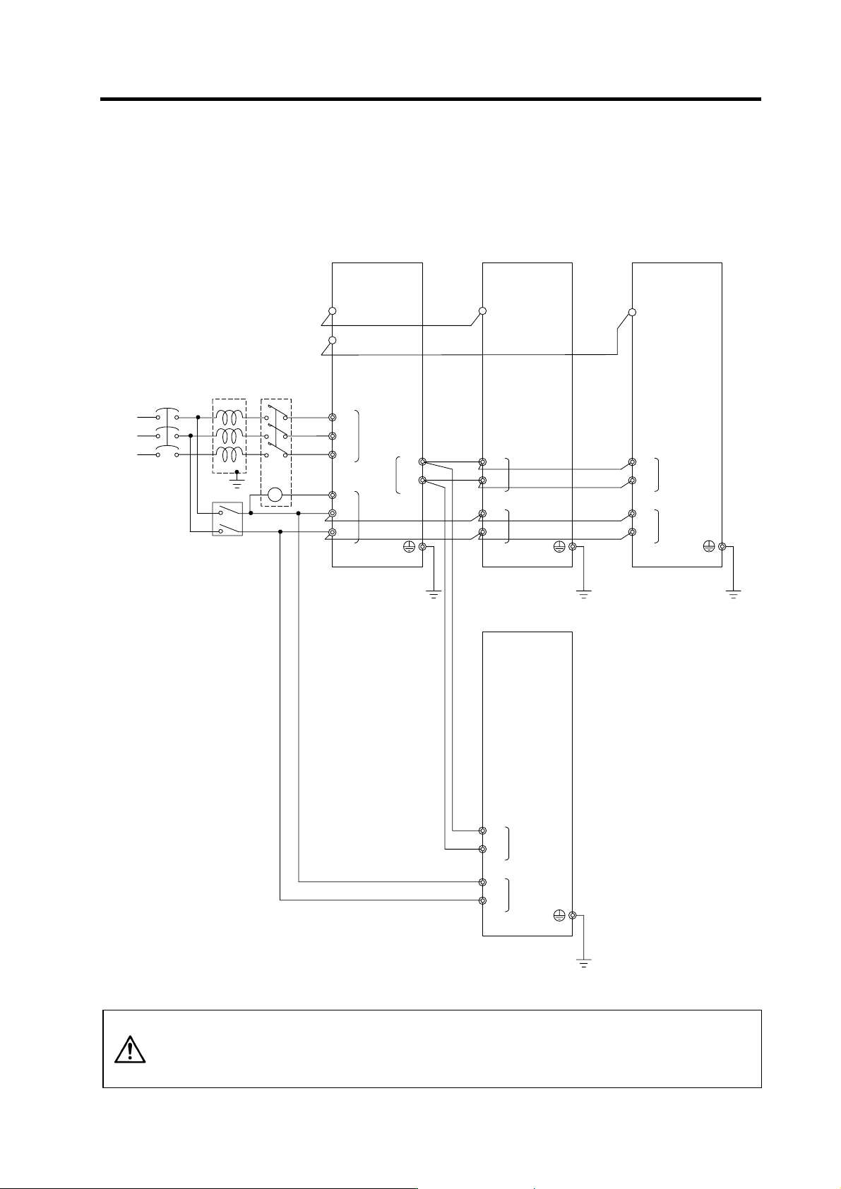
(3) When connecting one power supply unit with two spindle drive units
Only the spindle drive unit connected to the power supply unit's CN4 connector becomes the power
supply unit control axis.
MC1
T
S
R
Contacto
r
No-fuse
breaker
Ground
CN4
L1
L2
L3
L11
TE3
TE1
CN9
L+
L-
CN4
TE3
TE2
L+
L-
L11
L21
TE2
AC
reactor
Ground
Ground
L21
TE3
TE2
L+
L-
L11
L21
Ground
MC
Breake
r
CN4
MDS-C1-SPA(No.3)
TE3
TE2
L+
L-
L11
L21
Ground
MDS-C1-SPA(No.1) MDS-C1-CV MDS-C1-SPA(No.2)
CAUTION
1. When connecting two or more spindle drive units, install the large-capacity
drive units on both sides of the power supply unit.
2. Install units so that the “L+” and “L-” of each unit are in alignment and each
space between units is kept to 3cm or less.
2. Wiring and Connection
2 - 20
2-5-2 Connecting the grounding cable
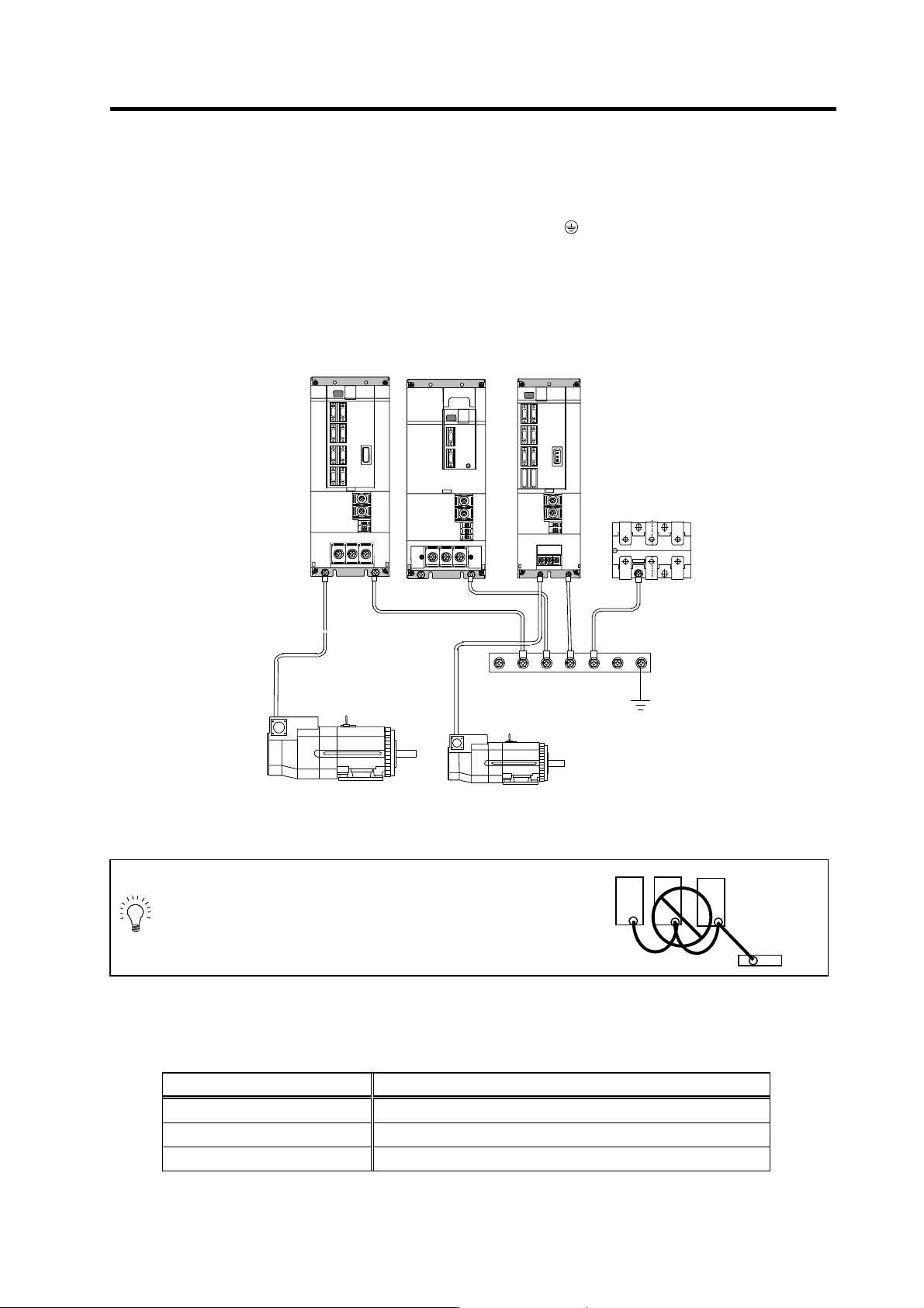
(1) Connecting the protective grounding (PE) and frame ground (FG)
Each unit has a terminal or mounting hole to connect PE (
) or FG.
Please connect an earth wire to the main ground of a cabinet or a machine frame at one point.
Ground each device according to the grounding conditions set forth by each country. (Typically, a
Y-connection neutral point ground is used in Europe.)
PE: Grounding to provide protection from electric shock, etc.
FG: Grounding to stabilize the operation of the devices, etc. (Suppress noise)
MDS-C1-SPA(No.1)
MDS-C1-CV
B-AL
SJ Series motor
Grounding plate
MDS-C1-SPA(No.2)
POINT
Do not connect the grounding cable from
each unit directly to the grounding plate.
Noise from other units could result in
malfunctions.
(2) Grounding cable size
Earth wire size should follow the following table.
Type Grounding cable size (Required grounding)
MDS-C1-CV Unit Larger than thickness of wire connected to TE1 (L1/L2/L3). (PE)
MDS-C1-SPA[] Unit Larger than thickness of wire connected to TE1 (U/V/W). (PE)
B-AL (AC Reactor) 5.5 mm
2
(AWG10) or more (FG)
Unit
Grounding
plate
Unit
Grounding
plate
2. Wiring and Connection
2 - 21
2-5-3 Main circuit control
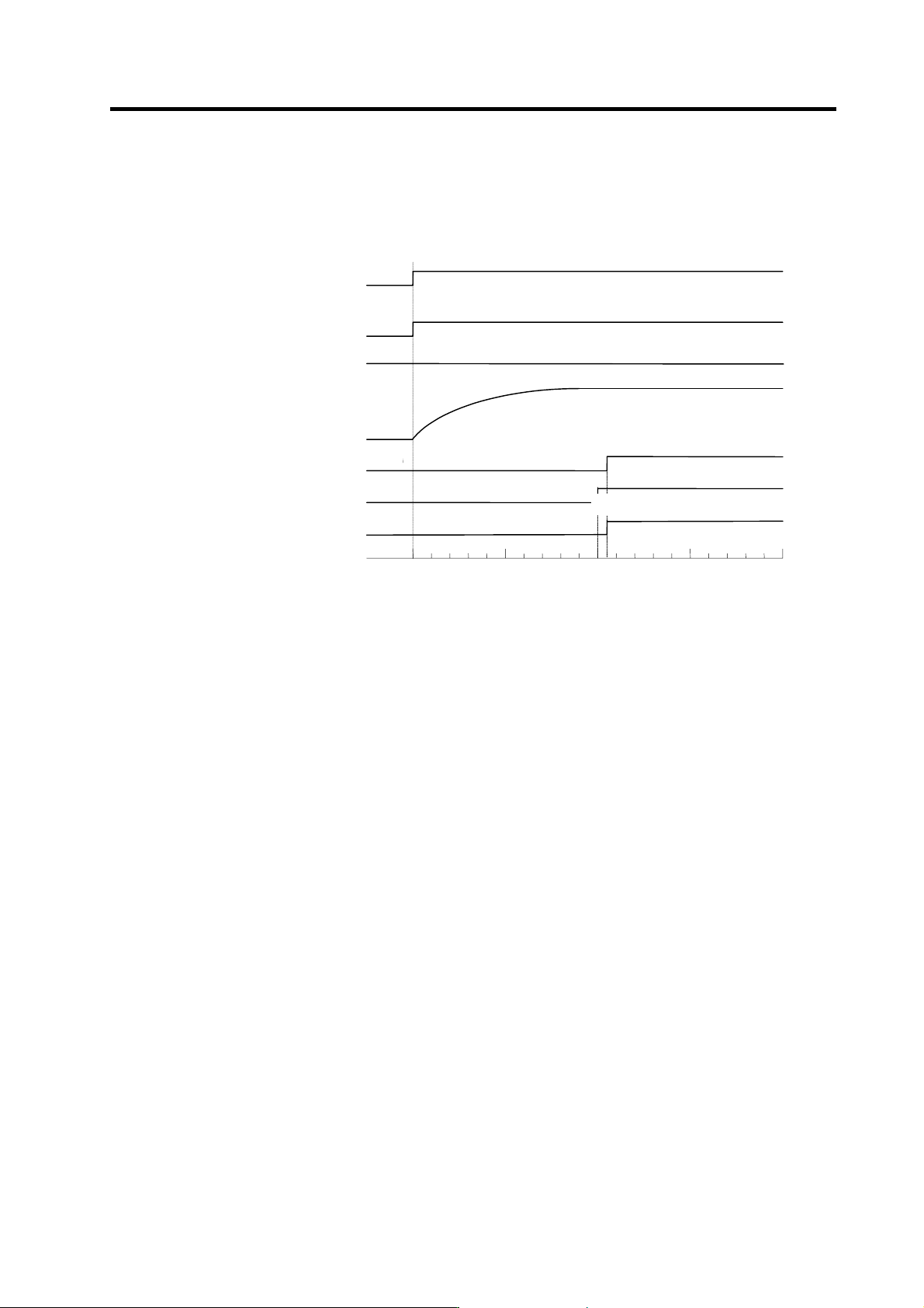
(1) Contactor ON sequence
Main circuit power is turned ON in the sequence shown below when an emergency stop status is
canceled.
OFF
ON
Machine ready complete input
signal (READY)
Emergency stop (EMG)
OFF
ON
Contactor co ntrol ou tp ut (MC1)
ON
OFF
Motor ON (GATE)
ON
OFF
ON
OFF
In read y ON signal (ron)
ON
OFF
Forward run/reverse run signal
(SRN, SRI)
0
500 1000 1500
Time (ms)
Command input enable
Ready completion
・
Contactor ON sequence
PN bus voltage
PN charging completed