MDS-C1-SPA Series INSTRUCTION MANUALib1500152(eng)a.pdf - 第203页
Appendix 1. Cable and Connector Specifications A1 - 4 Appendix 1-2 Cable connection diagram CAUTION 1. Do not mistake the connection when manufacturing the detector cable. Failure to observe this could l ead to faults, r…
Appendix 1. Cable and Connector Specifications
A1 - 3
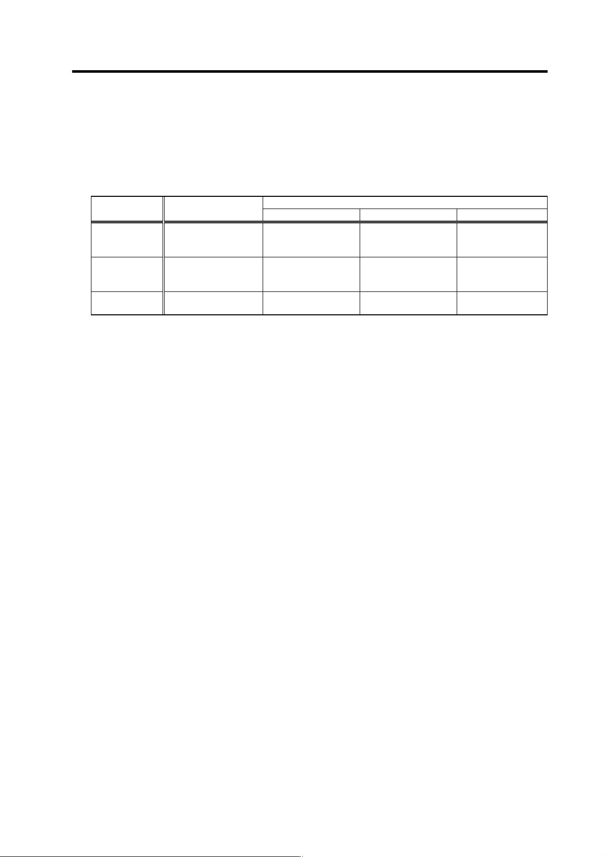
(3) Cable protection tube (noise countermeasure)
If influence from noise is unavoidable, or further noise resistance is required, selecting a flexible
tube and running the signal cable through this tube is effective. This is also an effective
countermeasure for preventing the cable sheath from being cut or becoming worn.
A cable clamp (MS3057) is not installed on the detector side, so be particularly careful of broken
wires in applications involving bending and vibration.
Connector
Supplier Tube
Drive unit side Installation screws Motor detector side
Nippon Flex
Control Corp.
FBA-4
(FePb wire braid sheath)
RBC-104 (straight)
RBC-204 (45°)
RBC-304 (90°)
G16
G16
G16
RCC-104-CA2022
DAIWA DENGYO
CO., LTD
Hi-flex
PT #17 (FePb sheath)
PSG-104 (straight)
PLG-17 (90°)
PS-17 (straight)
Screw diameter ø26.4
Screw diameter ø26.4
PF1/2
PDC20-17
Sankei Works
Purika Tube
PA-2 #17 (FePb sheath)
BC-17 (straight) Wire tube screws : 15 PDC20-17
(Note) None of the parts in this table can be ordered from Mitsubishi Electric Corp.
Appendix 1. Cable and Connector Specifications
A1 - 4
Appendix 1-2 Cable connection diagram
CAUTION
1. Do not mistake the connection when manufacturing the detector cable.
Failure to observe this could lead to faults, runaway or fires.
2. Do not connect anything to pins unless otherwise particularly specified when
manufacturing a cable. (Leave OPEN)
3. Contact Mitsubishi when manufacturing a cable longer than 30m.
4. Do not relay the cable which the shield cable is used in. Malfunctions may
occur due to noise from the motor drive wire, other cables or devices.
If the cable must be relayed, keep the peeled shield section as short as
possible (3cm or less), and separate the cable from the other drive wires and
cables. Mitsubishi will not be held liable for any problems that should occur
as a result of a relayed cable. The customer is responsible for providing
measures against noise.
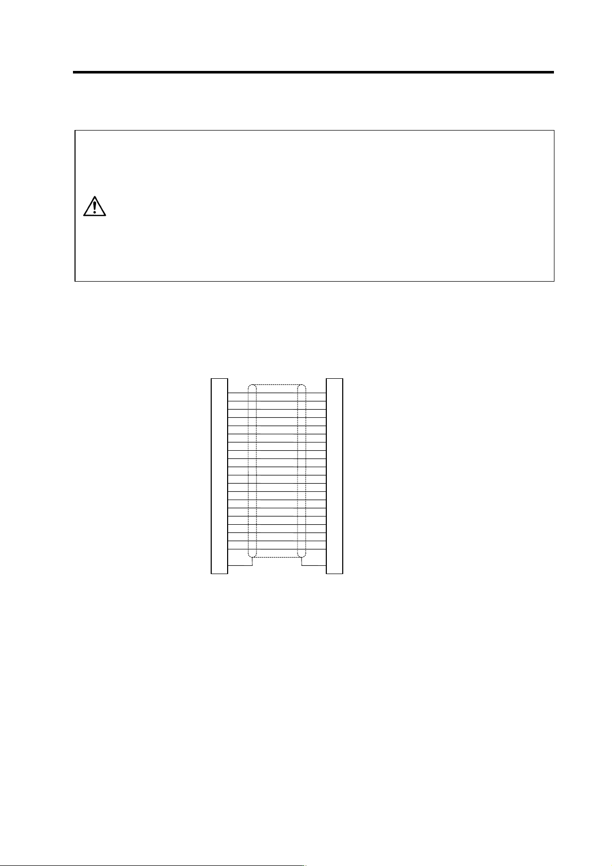
(1) NC bus cable (Cable between spindle drive unit and power supply unit)
<SH21 cable connection diagram>
Drive unit side connector
Connector: 10120-3000VE
Shell kit: 10320-52F0-008
Drive unit side connector
Connector: 10120-3000VE
Shell kit: 10320-52F0-008
1
11
2
12
3
13
4
14
5
15
6
16
7
17
8
18
9
19
10
20
PE
1
11
2
12
3
13
4
14
5
15
6
16
7
17
8
18
9
19
10
20
PE
FG
Appendix 1. Cable and Connector Specifications
A1 - 5
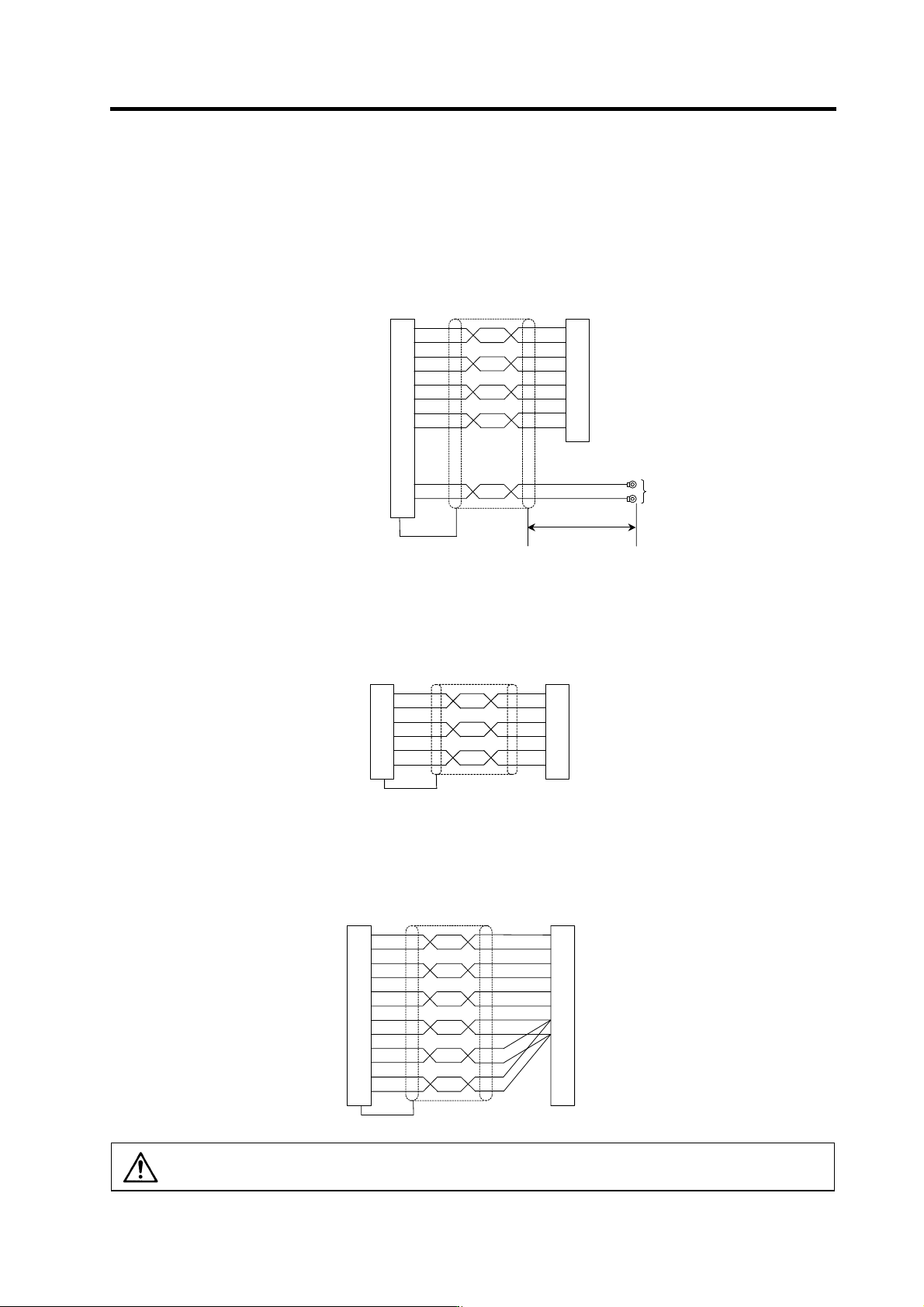
(2) Spindle detector cable
<CNP5 cable connection diagram>
6
16
7
17
8
5
1
5
1
3
13
P
A
R
A
PB
RB
PZ
P15(+15V)
N15(-15V)
LG
MOH
RG
(CN5) Spindle drive unit side
connector
Connector: 10120-3000VE
Shell kit: 10320-52F0-008
Motor PLG side connector
Housing: 350720-1
Pin: 35068 9-1
V1.25-4
100mm
1
2
3
4
5
8
6
9
<CNP6M cable connection diagram>
6
16
7
17
5
15
MAG
MAG
R
LS
LS
R
P15(+15V)
LG
A
D
F
E
C
B
Magnetic sensor side connector
Connector: TRC116-12A10-7F10.5
(CN6) Spindle drive unit side
connector
Connector: 10120-3000VE
Shell kit: 10320-52F0-008
<CNP6A cable connection diagram>
2
12
3
13
4
14
10
1
19
11
20
1
5
M
A
MA
*
MB
MB
*
MZ
MZ
*
P5(+5V)
LG
P5(+5V)
LG
P5(+5V)
LG
(CN6) Spindle drive unit side
connector
Connector: 10120-3000VE
Shell kit: 10320-52F0-008
Spindle side detector
(1024p/rev encoder)side connector
Plug: MS3106B20-29S (Straight)
MS3108B20-29S (Angle)
Clamp: MS305 7-12A
A
N
C
R
B
P
H
K
CAUTION
The shield of the spindle detector cable is not connected to the "FG" (earth). Do
not connect the cable shield to the earth by clamping the cable, etc.