MDS-C1-SPA Series INSTRUCTION MANUALib1500152(eng)a.pdf - 第172页
5 - 1 5. Troubleshooting 5-1 Points of caut ion and c onf irmation ........................................................................................ ........... 5-2 5-1-1 LED display when al arm or warni ng occu r…
4. Spindle Adjustment
4 - 80
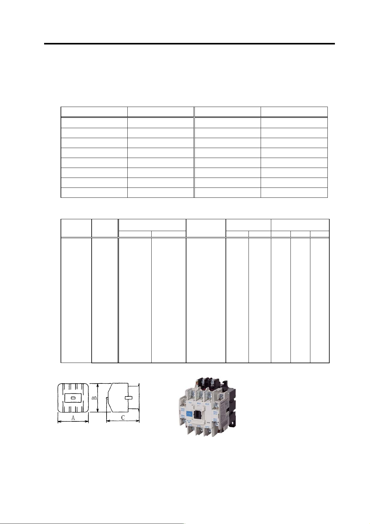
(6) Coil changeover contactor (magnetic contact)
[1] Selection
The coil changeover contac tor is selected according to the applicable spindle drive unit's capacity
as shown below.
Spindle drive unit type Applicable contactor type Spindle drive unit type Applicable contactor type
MDS-A/B-SPA(H)-040 S-N10 MDS-A/B/C1-SPA(H)-150 S-N50
MDS-A/B-SPA(H)-075 S-N10 MDS-A/B/C1-SPA(H)-185 S-N65
MDS-A/B-SPA(H)-15 S-N10 MDS-A/B/C1-SPA(H)-220 S-N80
MDS-A/B-SPA(H)-22 S-N10 MDS-A/B/C1-SPA(H)-260 S-N80
MDS-A/B-SPA(H)-37 S-N18 MDS-A/B/C1-SPA(H)-300 S-N125
MDS-A/B/C1-SPA(H)-55 S-N20 MDS-B-SPA(H)-370 S-N150
MDS-A/B/C1-SPA(H)-75 S-N25 MDS-B-SPA(H)-450 S-N180
MDS-A/B/C1-SPA(H)-110 S-N35 MDS-B-SPA(H)-550 S-N300
[2] Outline
AC Class 3 rated working
current (A)
Support contact Dimensions (mm)
Name Model
200 to 220V 380 to 440V
Rated
conductivity
current (A)
Standard Special A B C
Open type
Non-
reversible
type
S-N10
S-N11
S-N12
S-N18
S-N20
S-N21
S-N25
S-N35
S-N50
S-N65
S-N80
S-N95
S-N125
S-N150
S-N180
S-N220
S-N300
S-N400
S-N600
S-N800
11
13
13
18
20
20
26
35
50
65
80
100
125
150
180
220
300
400
630
800
7
9
9
13
20
20
25
32
48
65
80
93
120
150
180
220
300
400
630
800
20
20
20
25
32
32
50
60
80
100
135
150
150
200
260
260
350
450
660(800)
800(1000)
1a
1a
1a1b
—
1a1b
2a2b
2a2b
2a2b
2a2b
2a2b
2a2b
2a2b
2a2b
2a2b
2a2b
2a2b
2a2b
2a2b
2a2b
2a2b
1b
1b
2a
—
2a
—
—
—
—
—
4a4b
4a4b
4a4b
4a4b
4a4b
4a4b
4a4b
4a4b
4a4b
4a4b
43
43
53
43
63
63
75
75
88
88
100
100
100
120
138
138
163
163
290
290
78
78
78
79
81
81
89
89
106
106
124
124
150
160
204
204
243
243
310
310
78
78
78
81
81
81
91
91
106
106
127
127
136
145
174
174
195
195
234
234
S-N21 type

5 - 1
5. Troubleshooting
5-1 Points of caution and confirmation ................................................................................................... 5-2
5-1-1 LED display when alarm or warning occurs .............................................................................. 5-3
5-2 Protective functions list of units ........................................................................................................ 5-4
5-2-1 List of alarms.............................................................................................................................. 5-4
5-2-2 List of warnings .......................................................................................................................... 5-6
5-3 Troubleshooting ................................................................................................................................ 5-7
5-3-1 Troubleshooting at power ON.................................................................................................... 5-7
5-3-2 Troubleshooting for each alarm No. .......................................................................................... 5-8
5-3-3 Troubleshooting for each warning No......................................................................................5-21
5-3-4 Troubleshooting the spindle system when there is no alarm or warning................................. 5-22
5. Troubleshooting
5 - 2
5-1 Points of caution and confirmation
If an error occurs in the spindle drive unit, the warning or alarm will occur. When a warning or alarm
occurs, check the state while observing the following points, and inspect or remedy the unit according
to the details given in this section.
<Point s of confirmation>
[1] What is the alarm code display?
[2] Can the error or trouble be repeated? (Check alarm history)
[3] Are the spindle motor and spindle drive unit temperature and ambient temperature normal?
[4] Are the power supply unit, spindle drive unit and motor grounded?
[5] Was the unit accelerating, decelerating or running at a set speed? What was the speed?
[6] Is there any difference during forward and backward run?
[7] Was there a momentary power failure?
[8] Did the trouble occur during a specific operation or command?
[9] At what frequency does the trouble occur?
[10] Is a load applied or removed?
[11] Has the drive unit been replaced, parts replaced or emergency measures taken?
[12] How many years has the unit been operating?
[13] Is the power supply voltage normal? Does the state change greatly according to the time band?
CAUTION
1. This power supply unit uses a large capacity electrolytic capacitor. When the
CHARGE lamp on the front of the power supply unit is lit, voltage is still
present at the PN terminal (TE2). Do not touch the terminal block in this
state.
2. Before replacing the unit, etc., always confirm that there is no voltage at the
PN terminal (TE2) with a tester or wait at least 15 minutes after turning the
main power OFF.
3. The conductivity in the unit cannot be checked.
4. Never carry out a megger test on the drive unit or power supply unit as the
unit could be damaged.