MDS-C1-SPA Series INSTRUCTION MANUALib1500152(eng)a.pdf - 第92页
4 - 1 4. Spindle Adjustment 4-1 D/A output specificati ons for spindl e drive unit .......................................................................... ....... 4-2 4-1-1 D/A output spec ifications .................…
3. Setup
3 - 31
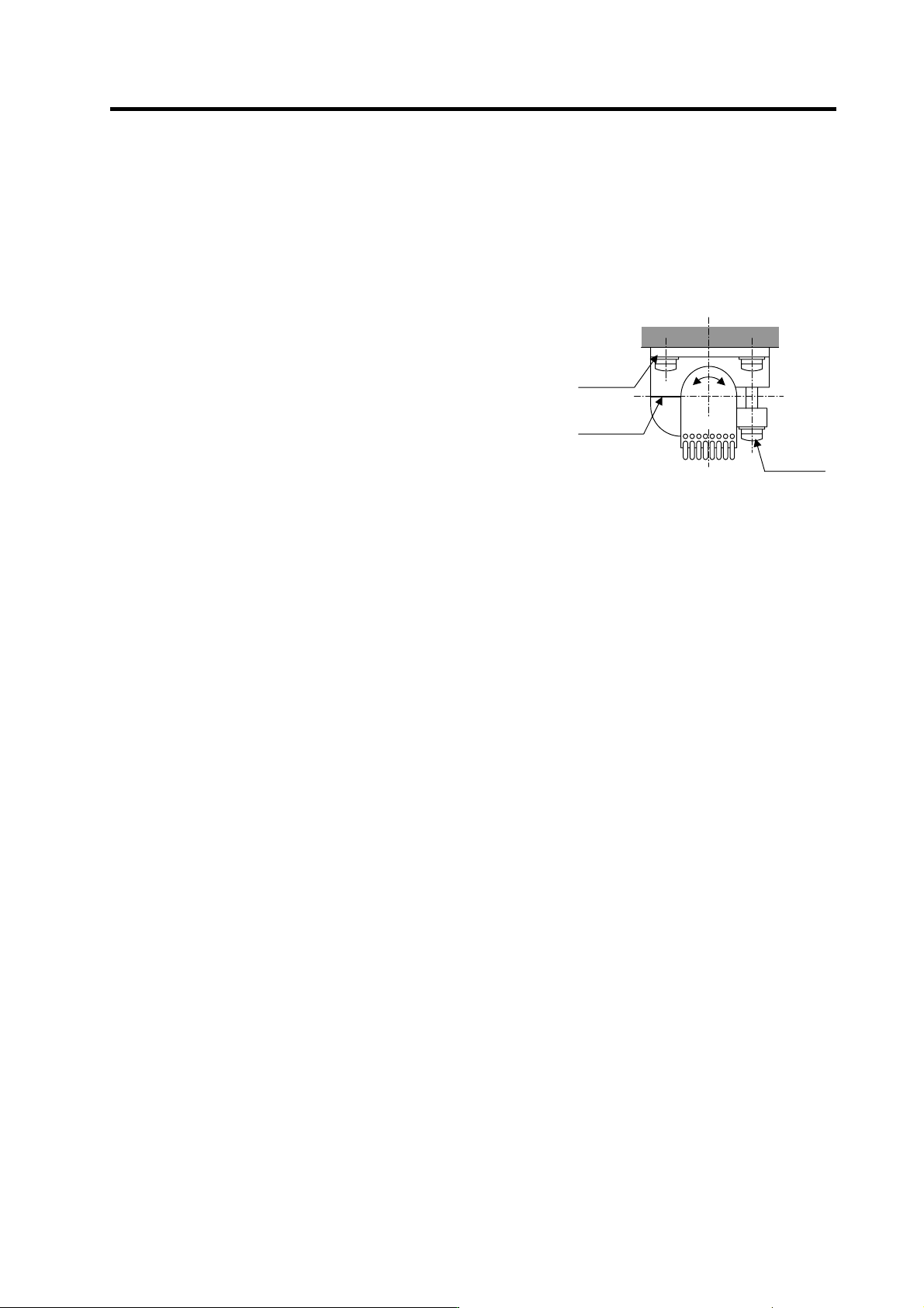
(8) Adjusting the Z phase and A phase difference
[1] Stop the motor, and make sure that the detection gears are not rotating. The sensor could be
damaged if adjustments are carried out while the gears are rotating.
[2] Using a clearance gauge, adjust so that the gap between the sensor direction surface and the
detection gears’ circumference is 0.15±0.01mm, and loosen the sensor fixing screw.
[3] The phase difference of the Z phase to the A phase can be adjusted by rotating the sensor as
shown on the right. At this time, rotate the sensor a little bit while using the marking lines on
the sensor and installation seat as a guide.
[4] Tighten the sensor fixing screw so that the sensor
does not move, and confirm that the gap between the
sensor detection surface and detection gears'
circumference is 0.15 ± 0.01mm. Then, rotate the
gears and confirm the phase difference as explained
above.
[5] When the phase difference is within the tolerable
range, apply a locking agent on the sensor fixing
screw, and then fix the sensor. Check the gap again
after fixing the sensor.
Marking
line
Rotate
Sensor
fixing
screw
Sensor
installation
seat
2.1.1.1.1Adjustin

4 - 1
4. Spindle Adjustment
4-1 D/A output specifications for spindle drive unit................................................................................. 4-2
4-1-1 D/A output specifications ........................................................................................................... 4-2
4-1-2 Setting the output data............................................................................................................... 4-2
4-1-3 Setting the output magnification ................................................................................................ 4-3
4-2 Spindle control signal........................................................................................................................ 4-5
4-2-1 Spindle control input (NC to SP) ................................................................................................ 4-5
4-2-2 Spindle control output (SP to NC)............................................................................................ 4-15
4-3 Adjustment procedures for each control......................................................................................... 4-27
4-3-1 Basic adjustments.................................................................................................................... 4-27
4-3-2 Adjusting the acceleration/deceleration operation................................................................... 4-30
4-3-3 Adjusting the orientation control .............................................................................................. 4-39
4-3-4 Adjusting the multi-point indexing orientation control .............................................................. 4-55
4-3-5 Adjusting S-analog high-speed tapping control ....................................................................... 4-64
4-3-6 Adjusting coil changeover........................................................................................................ 4-69
4. Spindle Adjustment
4 - 2
4-1 D/A output specifications for spindle drive unit
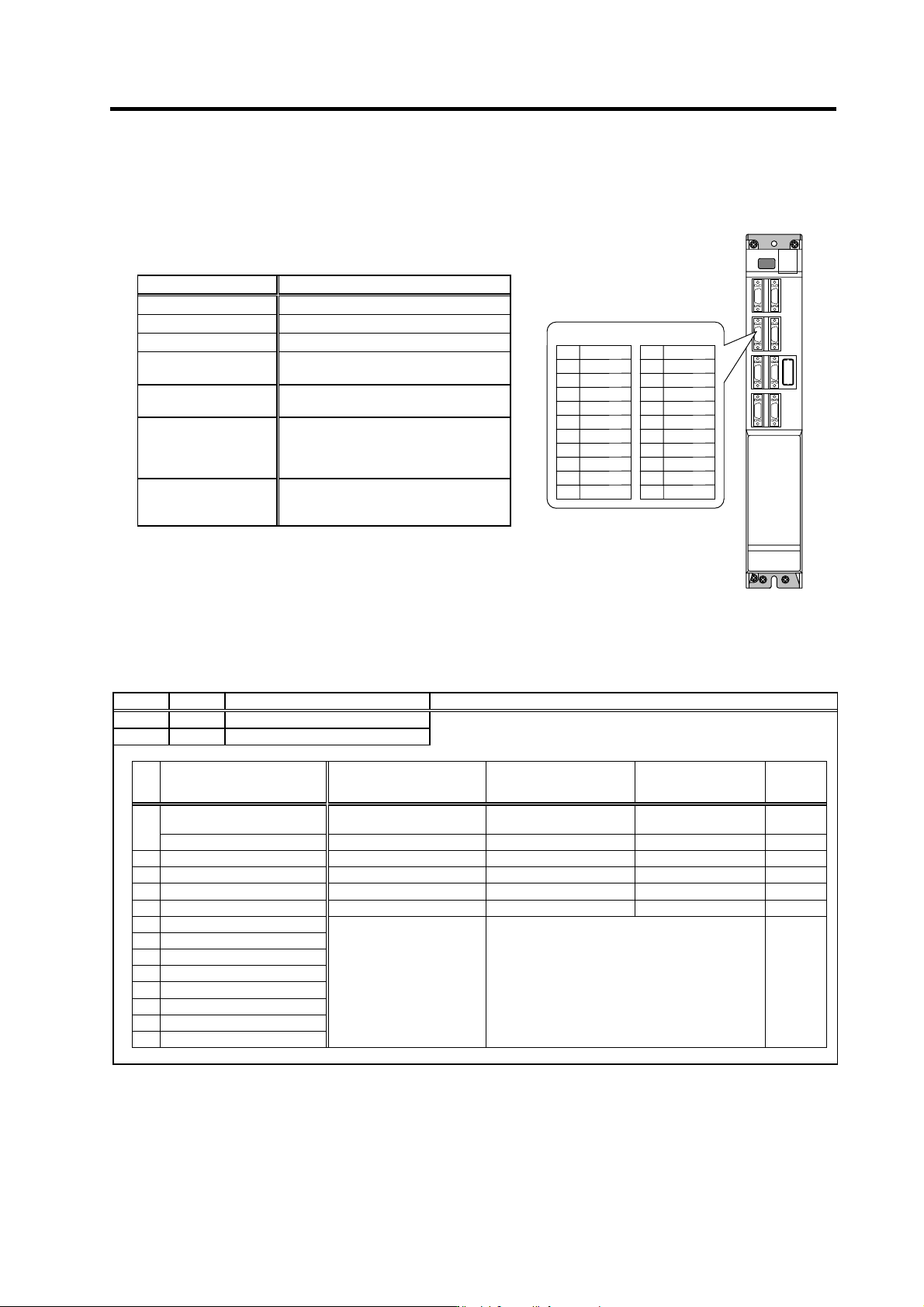
The spindle drive unit has a function to D/A output each control data. The spindle adjustment data
required to set the spindle parameters matching the machine can be D/A output. The data can be
measured with a hi-corder or oscilloscope, etc.
4-1-1 D/A output specifications
4-1-2 Setting the output data
No. Abbr. Parameter name Explanation
SP253 DA1NO
D/A output channel 1 data No.
Input the No. of the data to be output to each D/A output channel.
SP254 DA2NO
D/A output channel 2 data No.
No. Output data Original data unit
Output magnification
standard setting value
(SP255, SP256)
Output unit for
standard setting
Output
cycle
ch1: Speedometer output 10V=max. speed (Zero=0V) 0
Depends on maximum
speed
3.55ms
0
ch2: Load meter output 10V=120% load (Zero=0V) 0 30-minute rating 12%/V 3.55ms
1 –
2 Current command Rated 100%=4096 8 30-minute rating 20%/V 3.55ms
3 Current feedback Rated 100%=4096 8 30-minute rating 20%/V 3.55ms
4 Speed feedback r/min 13 500rpm/V 3.55ms
80 Control input 1
81 Control input 2
82 Control input 3
83 Control input 4
84 Control output 1
HEX Bit correspondence 3.55ms
85 Control output 2
86 Control output 3
87 Control output 4
Item Explanation
No. of channels 2ch
Output cycle 444µs (min. value)
Output precision 8bit
Output voltage range
0V to +5V (zero) to +10V,
0V to +10V for meter output
Output magnification
setting
±1/256 to ±128-fold
Output pin
CN9 connector
SMO = Pin 9 (D/A channel1)
LMO = Pin 19 (D/A channel2)
GND = Pin 1
Function
Phase current feedback output function
IU (U phase current FB) : Pin 7
IV (V phase current FB) : Pin 17
SMO9
Name
GND
IU
2
5
1
Pin
6
4
3
10
7
8
CN9 connector
LMO 19
Name
IV
12
15
11
Pin
16
14
13
20
17
18