MDS-C1-SPA Series INSTRUCTION MANUALib1500152(eng)a.pdf - 第182页
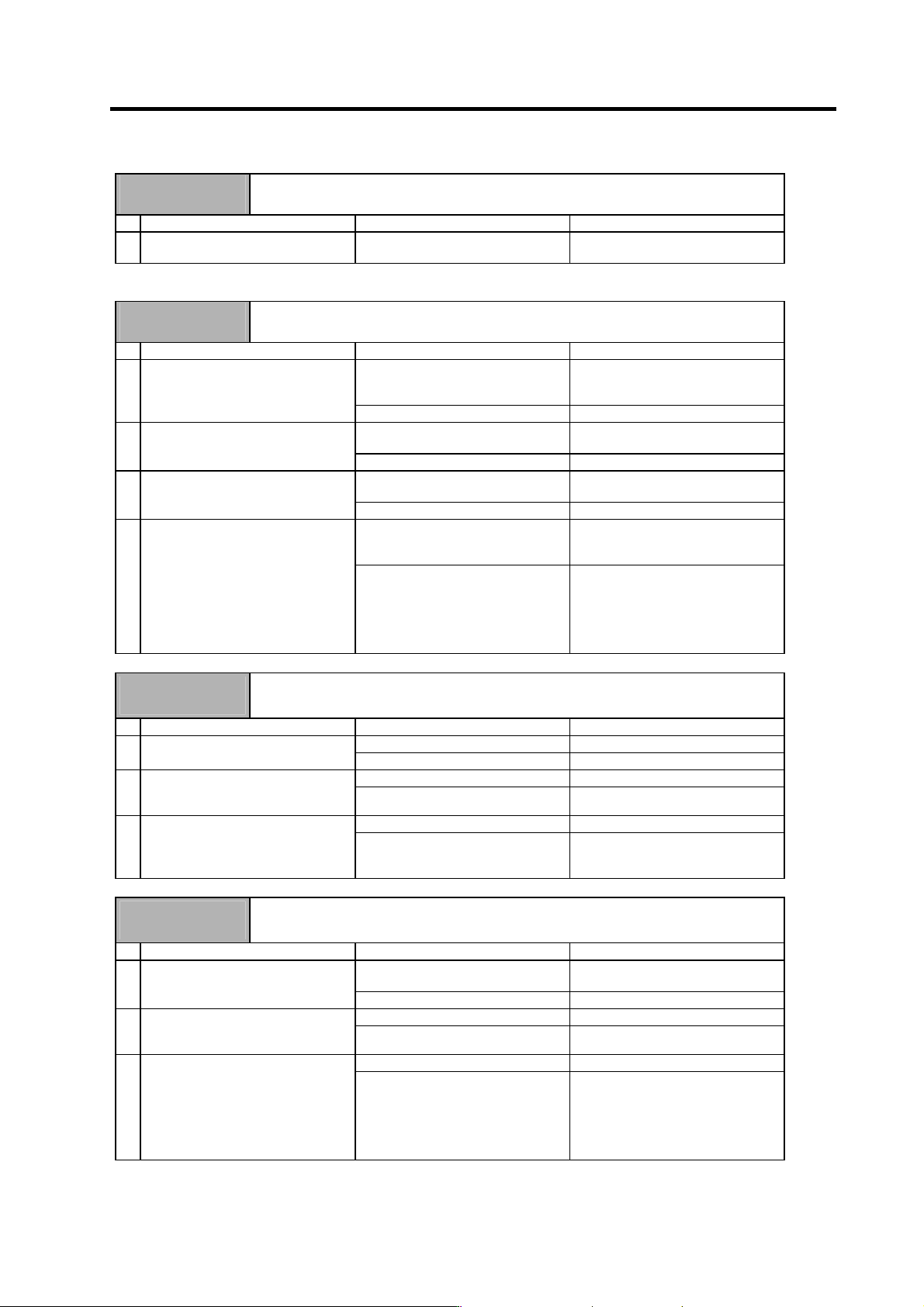
5. Troubleshooting 5 - 11 Alarm No. 37 Initial parameter error An illegal parameter was detected at power ON. Investigation details Investigation results Remedies 1 Check the erro r parameter No. SP001 to SP384 Set the v…
5. Troubleshooting
5 - 10
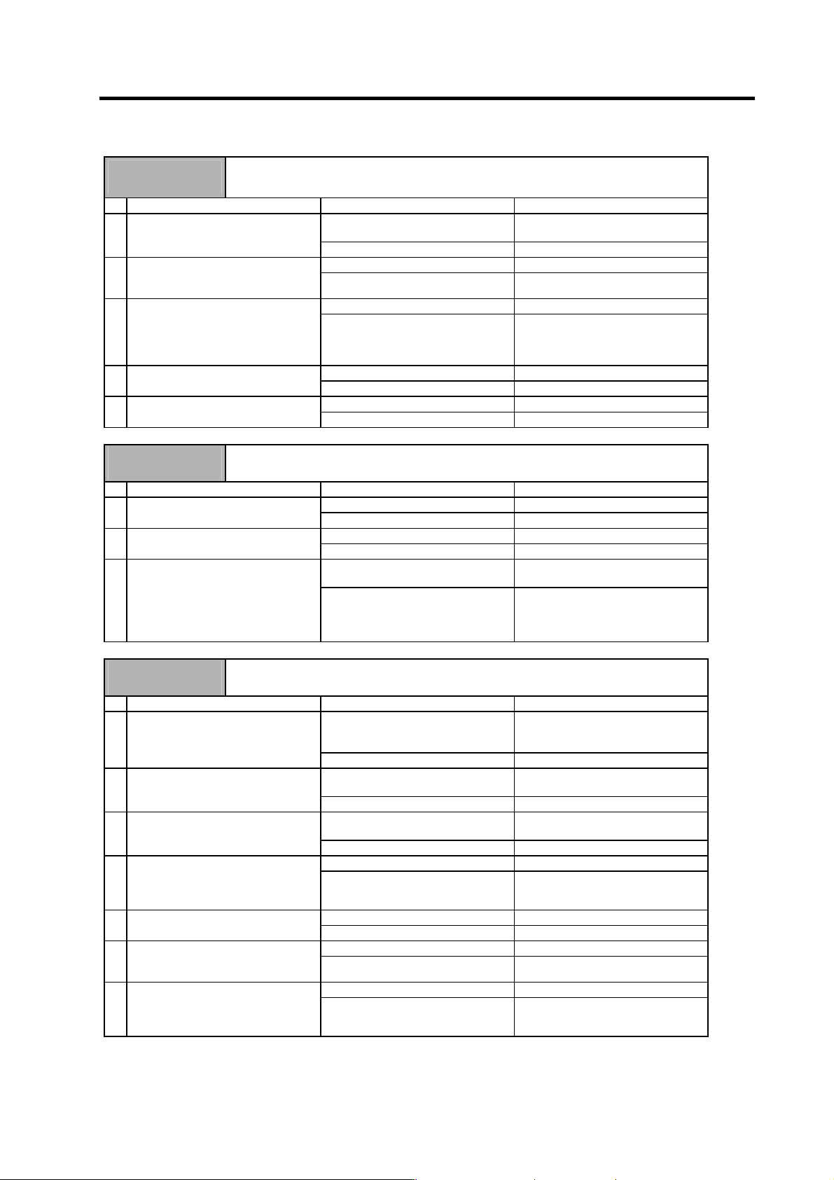
Alarm No.
23
Excessive speed deflection 1
A difference of 50r/min or more between the speed command and speed feedback continued
for longer than the set time. (Time is a value set to SP055.)
Investigation details Investigation results Remedies
The wires are not correctly
connected.
Correctly connect. 1 Check the U, V and W wiring
between the spindle drive unit and
spindle motor.
The wires are correctly connected. Investigate item 2.
The correct values are not set. Correctly set. 2 Check the settings for SP034,
SP040, SP055, and SP257 to
SP384.
The correct values are set. Investigate item 3.
12 seconds or more. Increase the SP055 setting value. 3 Measure the acceleration/
deceleration time constants.
Measure the time required to reach
the reverse run maximum speed from
the forward run maximum speed.
Less than 12 seconds. Investigate item 4.
120% or more. Reduce the load. 4 Measure the load during cutting.
Less than 120%. Investigate item 5.
There is a problem. Adjust the PLG output waveform. 5 Check the PLG output waveform.
Normal. Replace the drive unit.
Alarm No.
31
Overspeed
A rotation speed exceeding the motor's tolerable rotation speed was detected.
Investigation details Investigation results Remedies
Setting value is too small. Correctly set. 1 Confirm the spindle parameter
SP017 (TSP) setting.
Correctly set. Investigate item 4.
There is a problem. Adjust the PLG output waveform. 2 Confirm the PLG output waveform.
Normal. Investigate item 5.
The waveform is overshooting. Increase the acceleration/
deceleration time constant.
3 Check whether the speed waveform
is overshooting.
The waveform is not overshooting. Check if there is any abnormality in
the unit's ambient environment.
(Ex.: Ambient temperature, noise,
grounding)
Alarm No.
32
Power module overcurrent
The power module's overcurrent protection function activated.
Investigation details Investigation results Remedies
The alarm occurs before READY ON.
(The drive unit is faulty.)
Check investigation item 2 and
following, and remove the cause of
the fault. Then replace the drive unit.
1 Check the repeatability.
The alarm occurs after READY ON. Investigate item 2.
The setting is incorrect.
SP034,SP040,SP257 to SP384
Correctly set. 2 Check the parameter setting.
• Motor type
The setting is correct. Investigate item 3.
The setting is large compared to the
standard value.
Set the standard value. 3 Check the parameter settings.
• Current loop gain
• Speed loop gain
The standard value is set. Investigate item 4.
The power cable is short-circuited. Replace the motor's power cable. 4 Disconnect the UVW phase wiring
from the terminal block, and the UVW
phase of the motor from the motor.
Check the insulation with a tester.
There is no problem. Investigate item 5.
The power cable is short-circuited. Replace the motor's power cable. 5 Check the insulation between the
motor power cable and FG.
There is no problem. Investigate item 6.
The motor is short-circuited. Replace the motor. 6 Connect the UVW phase of the
motor, and check the insulation
between the power cable and FG.
There is no problem. Investigate item 7.
No abnormality is found in particular. Replace the drive unit. 7 Check for any abnormalities in the
motor's ambient environment.
(Ex.: Ambient temperature, cutting
water)
An abnormality was found in the
ambient environment.
Replace the motor and improve the
motor installation environment.
5. Troubleshooting
5 - 11
Alarm No.
37
Initial parameter error
An illegal parameter was detected at power ON.
Investigation details Investigation results Remedies
1 Check the error parameter No. SP001 to SP384 Set the value within the designated
setting range.
(Note) Refer to "5-3-4 Parameter numbers at initial parameter error".
Alarm No.
3B
Power module overheat
The power module's temperature protection function activated.
Investigation details Investigation results Remedies
Large amounts of cutting oil or cutting
chips, etc., are adhered, or the
rotation is slow.
Clean or replace the fan. 1 Confirm that the fan is rotating
correctly.
The fan is rotating properly. Investigate item 2.
Cutting oil or cutting chips, etc., are
adhered, and the fins are clogged.
Clean the fins. 2 Check whether the heat dissipating
fins are dirty.
The fins are normal. Investigate item 3.
55°C or more Improve the ventilation and cooling
for the power distribution panel.
3 Measure the drive unit's ambient
temperature.
Less than 55°C. Investigate item 4.
No abnormality is found in particular. If the alarm occurs even after the unit
temperature has dropped, replace
the unit.
4 Check if there is any abnormality in
the unit's ambient environment.
(Ex. Ambient temperature, noise,
grounding)
An abnormality was found in the
ambient environment.
Take remedies according to the
causes of the abnormality.
Ex. High temperature:
Check the cooling fan.
Incomplete grounding:
Additionally ground.
Alarm No.
3F
Speed excessive deflection 2
During constant speed operation, the difference between the speed command and speed
feedback exceeded the set amount and set time.
Investigation details Investigation results Remedies
The cutting load is large. Lower the cutting load. 1 Check the load value, and investigate
the machine's load state.
The cutting load is not large. Investigate item 2.
Locked with a mechanical lock. Remove the cause of the lock. 2 Check whether the spindle rotary
section is locked with a mechanical
lock (C-axis clamp, etc.).
Not locked with a mechanical lock. Investigate item 3.
Improved. Replace the drive unit. 3 Try replacing the drive unit.
Not improved. Investigate the motor.
(Check the motor type and
parameters.)
Alarm No.
40
Detector changeover unit, changeover error
During 1-drive unit 2-motor control, an error was detected in the motor changeover signal
received form the detector changeover unit.
Investigation details Investigation results Remedies
The connector is disconnected (or
loose).
Correctly install. 1 Wiggle the FR-TK unit connector by
hand to check whether it is
disconnected.
The connector is not disconnected. Investigate item 2.
The cable is broken. Replace the cable. 2 Check whether the cable connected
between the spindle drive unit and
FR-TK unit is broken.
The cable is not broken. Investigate item 3.
No abnormality is found in particular. Replace the drive unit. 3 Check if there is any abnormality in
the unit's ambient environment.
(Ex. Ambient temperature, noise,
grounding)
An abnormality was found in the
ambient environment.
Take remedies according to the
causes of the abnormality.
Ex. High temperature:
Check the cooling fan.
Incomplete grounding:
Additionally ground.
5. Troubleshooting
5 - 12
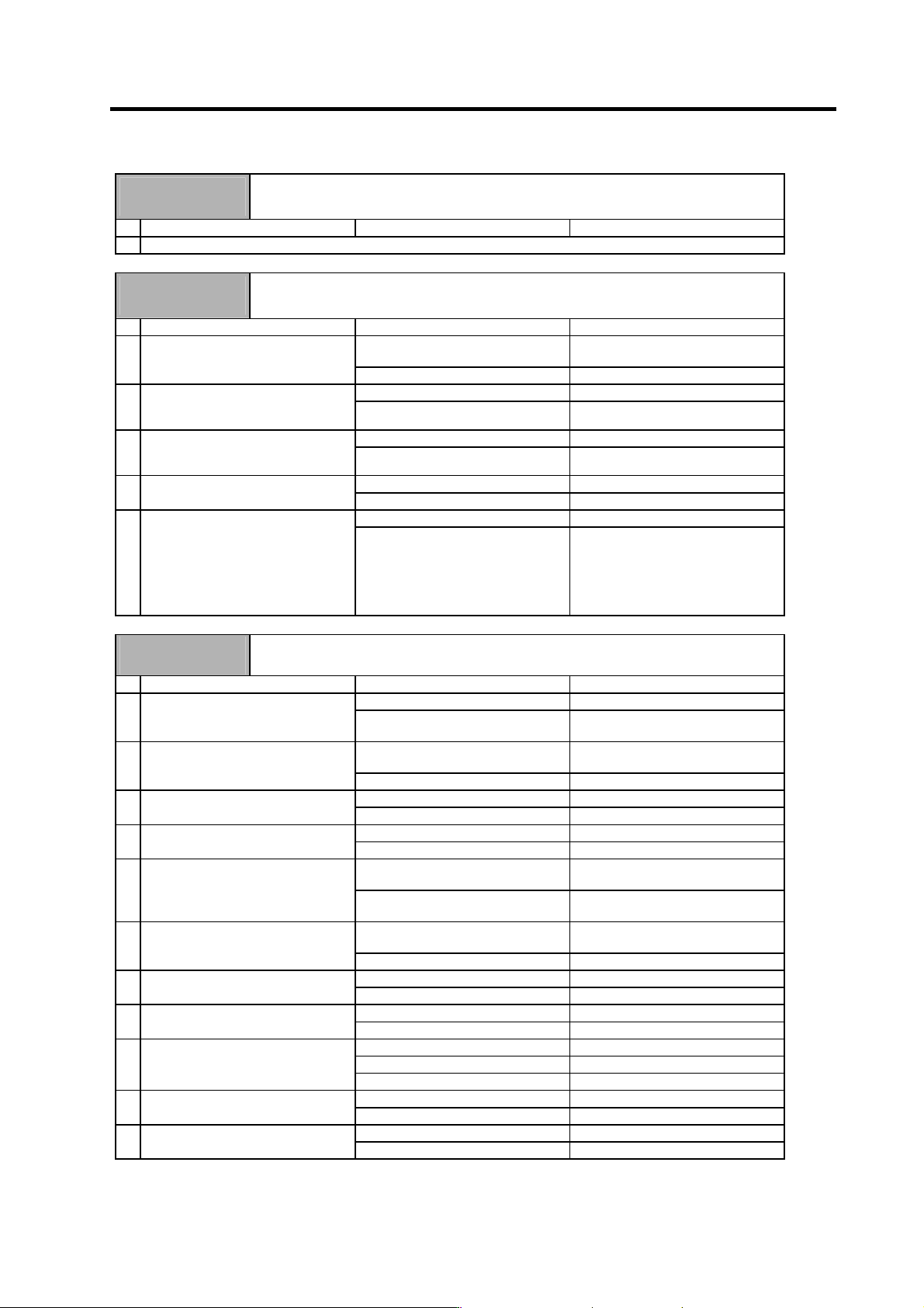
Alarm No.
41
Detector changeover unit, communication error
During 1-drive unit 2-motor control, an error was detected in the communication with the
detector changeover unit.
Investigation details Investigation results Remedies
1 Check the alarm No. "40" items.
Alarm No.
42
Feedback error 1
With the servo, pulse-type position detector feedback signal error was detected. With the
spindle, a PLG feedback signal error was detected.
Investigation details Investigation results Remedies
The connector is disconnected (or
loose).
Correctly install. 1 Check whether the drive unit
connectors (CN6) or detector
connectors are disconnected.
The connector is not disconnected. Investigate item 2.
There is a connection fault. Replace the detector cable. 2 Turn the power OFF, and check the
detector cable connection with a
tester.
The connection is normal. Investigate item 3.
The alarm is on the drive unit side. Replace the drive unit. 3 Connect to another normal drive unit,
and check whether the fault is on the
drive unit side or detector side.
The alarm is on the detector side. Investigate item 4.
There is a problem. Adjust the PLG output waveform. 4 Check the PLG output waveform.
Normal Investigate item 5.
No abnormality is found in particular. Replace the detector. 5 Check if there is any abnormality in
the detector's ambient environment.
(Ex. Ambient temperature, noise,
grounding)
An abnormality was found in the
ambient environment.
Take remedies according to the
causes of the abnormality.
Ex. High temperature:
Check the cooling fan.
Incomplete grounding:
Additionally ground.
Alarm No.
46
Motor overheat
The temperature protection function in the motor or detector activated.
Investigation details Investigation results Remedies
The alarm occurs before operation. Investigate item 2. 1 Check the repeatability.
The alarm occurs occasionally after
operation is started.
Investigate item 4.
The connector is disconnected (or
loose).
Correctly install. 2 Check whether the drive unit
connectors (CN6) or detector
connectors are disconnected.
The connector is not disconnected. Investigate item 3.
The cable is broken. Replace the cable. 3 Using a tester, check whether the
detector cable is broken.
The cable is not broken. Investigate item 11.
The load is large. Investigate item 7. 4 Check the load meter (spindle).
The load is not large. Investigate item 8.
The constant load torque (friction +
unbalance) is 60% or more.
Select the motor so that the constant
load torque is 60% or less.
5 Is the unbalance torque high?
The constant load torque is less than
60%.
Investigate item 6.
The alarm was forcibly reset. Do not turn the drive unit's power
OFF when an overload alarm occurs.
6 Was the overload alarm (50) forcibly
reset by turning the drive unit power
OFF?
The alarm was not forcibly reset. Investigate item 8.
There was an incorrect setting. Correctly set. 7 Check the parameter settings.
The settings are correct. Investigate item 8.
Hot. Investigate item 9. 8 Measure the motor temperature
when the alarm occurs.
Not hot. Investigate item 11.
The fan motor was stopped. Investigate item 10.
The motor fan wind flow is poor. Clean.
9 When using a motor with fan, check
whether the fan is stopped, or
whether it is clogged with dust, etc.
There is no problem. Investigate item 11.
The cable is broken. Replace the cable. 10 Check the fan wiring.
The cable is not broken. Replace the fan.
Improved. Replace the drive unit. 11 Try replacing the drive unit.
Not improved. Replace the motor.