MDS-C1-SPA Series INSTRUCTION MANUALib1500152(eng)a.pdf - 第125页
4. Spindle Adjustment 4 - 34 (5) Adjusting speed command dual-cushion When a deceleration start causes rippling in the phase current FB waveform, or when a spindle override change cau s es gear impa ct noise, the paramet…
4. Spindle Adjustment
4 - 33
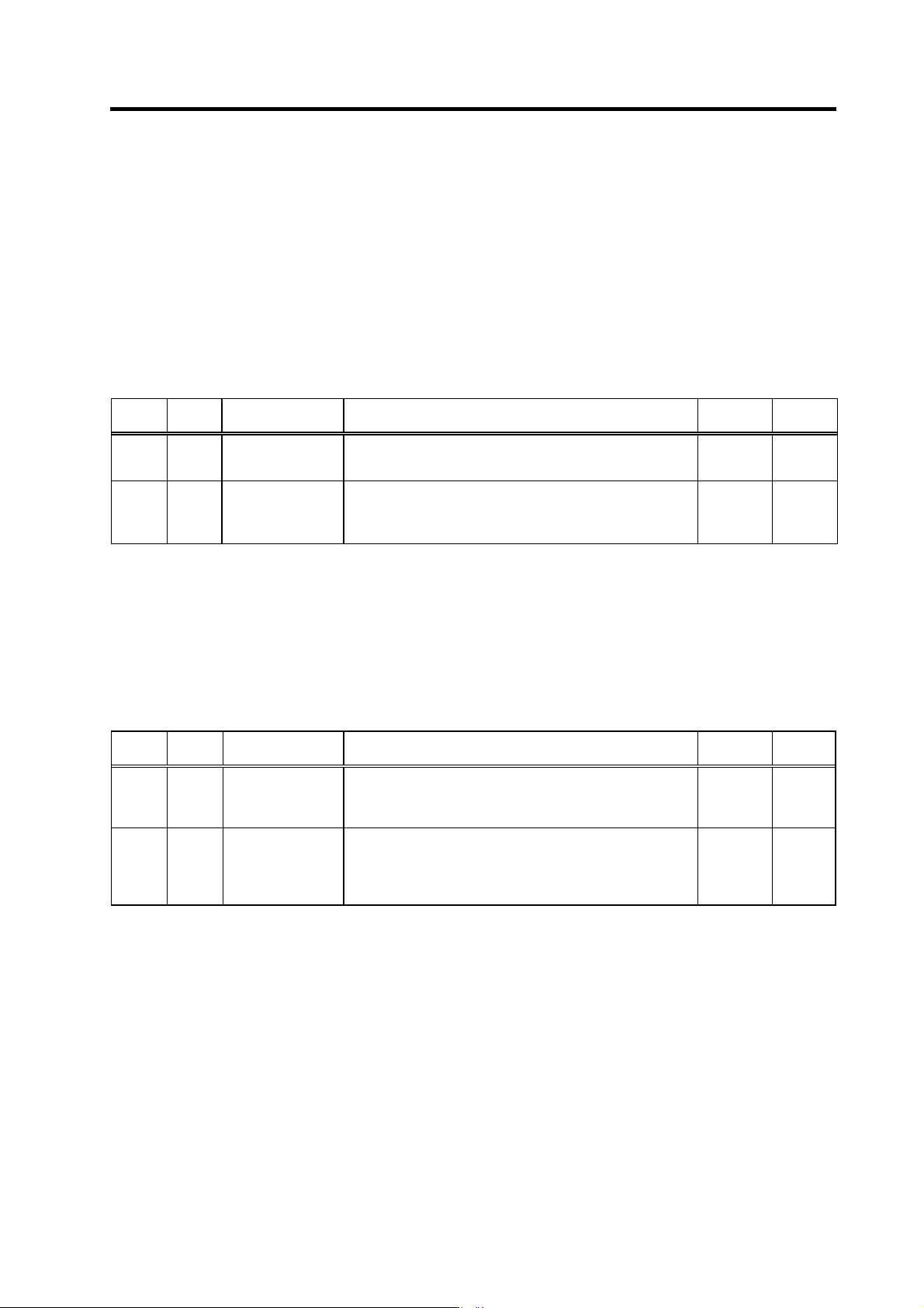
(3) Adjustment when the load inertia is large
When the load inertia is large and acceleration time is 10s or more, excessive speed deviation
alarm (ALM23) may occur because the time in which deviation between speed command and
speed FB, which is the actual spindle motor rotation speed, exists is prolonged. In this case,
increase the parameter SP019(CSN1). When the accele ration time is 10s or less, use the standard
value 30 (300ms).
Alarm can be avoided by adjusting the parameter SP055(SETM). However, in this case, alarm
detection will be delayed during constant speed operation.
In order to improve current ripple waveforms during acceleration/deceleration, adjust by using
speed command dual cushion explained later.
No. Abbr. Parameter name Details
Setting
range
Standard
SP019 CSN1* Speed cushion 1 Set the time constant for a speed command from "0" to the
maximum speed.
(This parameter is invalid during position loop control.)
1 to 32767
(10ms)
30
SP055 SETM* Excessive speed
deviation timer
Set the timer value until the excessive speed deviation alarm is
output.
The value of this parameter should be longer than the
acceleration/deceleration time.
0 to 60
(s)
12
(4) Adjustment when machine system vibration (noise) is generated
When machine components such as gears produce vibration and noise, a machine resonance
suppressing filter (notch filter) can be set to eliminate the vibration. At the p arameter SP070(FHz),
specify the frequency of the vibration to be eliminated. This filter is enabled during all positioning
control modes, including speed control, orientation control, and synchronous tap control. If
vibration is generated or increased by setting this filter at low speeds, set the parameter
SP076(FONS) to prevent the vibration.
No. Abbr. Parameter name Details
Setting
range
Standard
SP070 FHz Machine resonance
suppression filter
frequency
When machine vibration occurs in speed and position control,
set the frequency of the required vibration suppression.
Note that a value of 100Hz or more is set.
Set to "0" when not used.
0 to 3000
(Hz)
0
SP076 FONS Machine resonance
suppression filter
operation speed
When the vibration increases in motor stop (ex. in orientation
stop) when the machine vibration suppression filter is operated
by SP070, operate the machine vibration suppression filter at a
speed of this parameter or more.
When set to "0", this is validated for all speeds.
0 to 32767
(r/min)
0
4. Spindle Adjustment
4 - 34
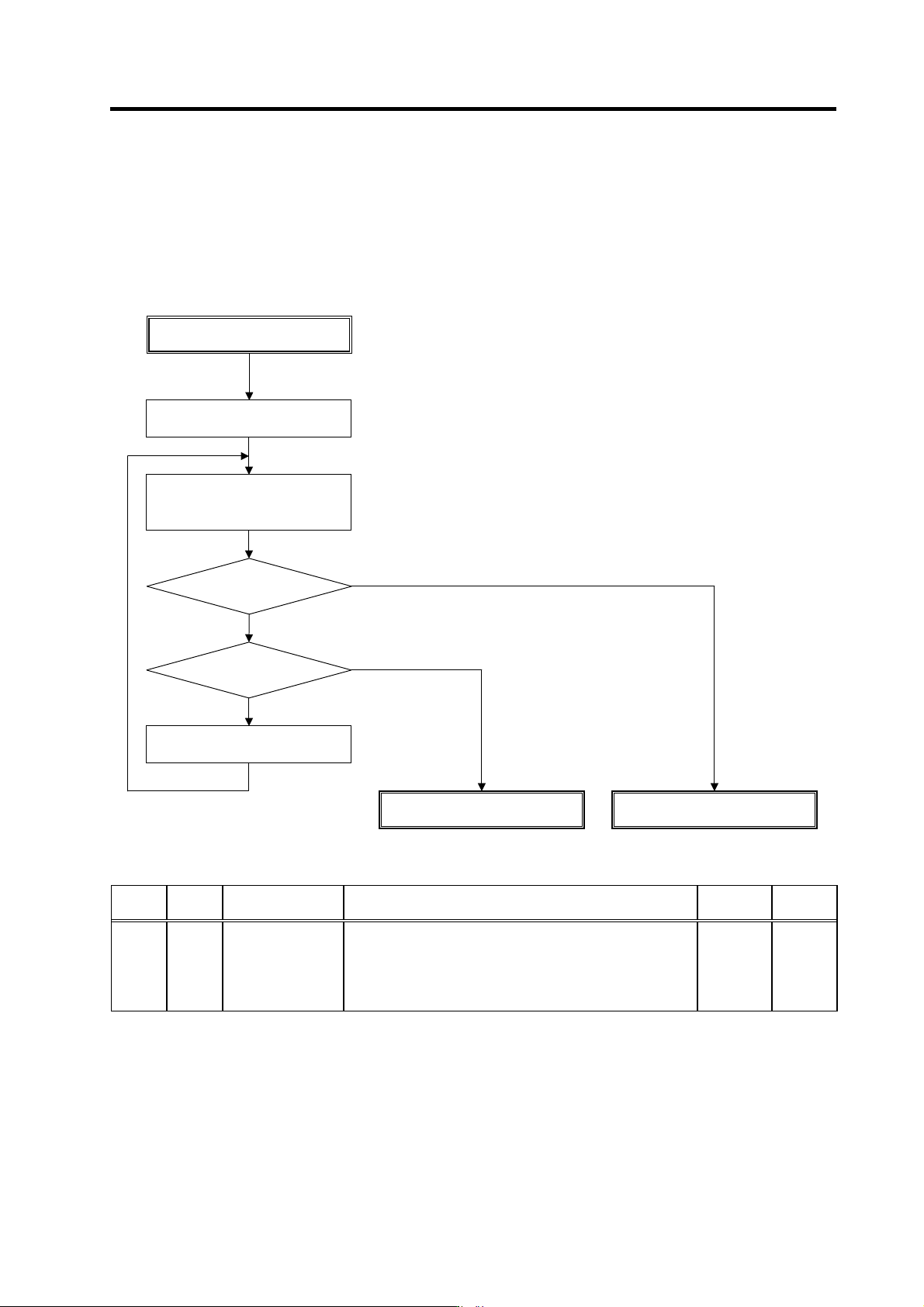
(5) Adjusting speed command dual-cushion
When a deceleration start causes rippling in the phase current FB waveform, or when a spindle
override change causes gear impact noise, the parameter SP046(CSN2) setting should be
adjusted. The smaller the SP046 setting value, the longer the acceleration/deceleration time.
Therefore, set SP046 value as high as possible, while observing the phase current FB waveform,
or while listening to the impact noise. (Setting upper limit = 5)
No. Abbr. Parameter name Details
Setting
range
Standard
SP046 CSN2* Speed command
dual cushion
For an acceleration/deceleration time constant defined in
SP019 (CSN1) , this parameter is used to provide smooth
movement only at the start of acceleration/deceleration.
As the value of this parameter is smaller, it moves smoother but
the acceleration/deceleration time becomes longer.
To make this parameter invalid, set "0".
0 to 1000 0
Adjusting SP046
Does waveform ripple or
impact noise occur?
Check for other causes
NO
Measure acceleration/deceleration
waveform at high speed
Change the spindle override
Increase SP046 by –1.
YES
Set SP046=5
YES
NO
SP046 adjustment completed
SP046=1 ?
4. Spindle Adjustment
4 - 35
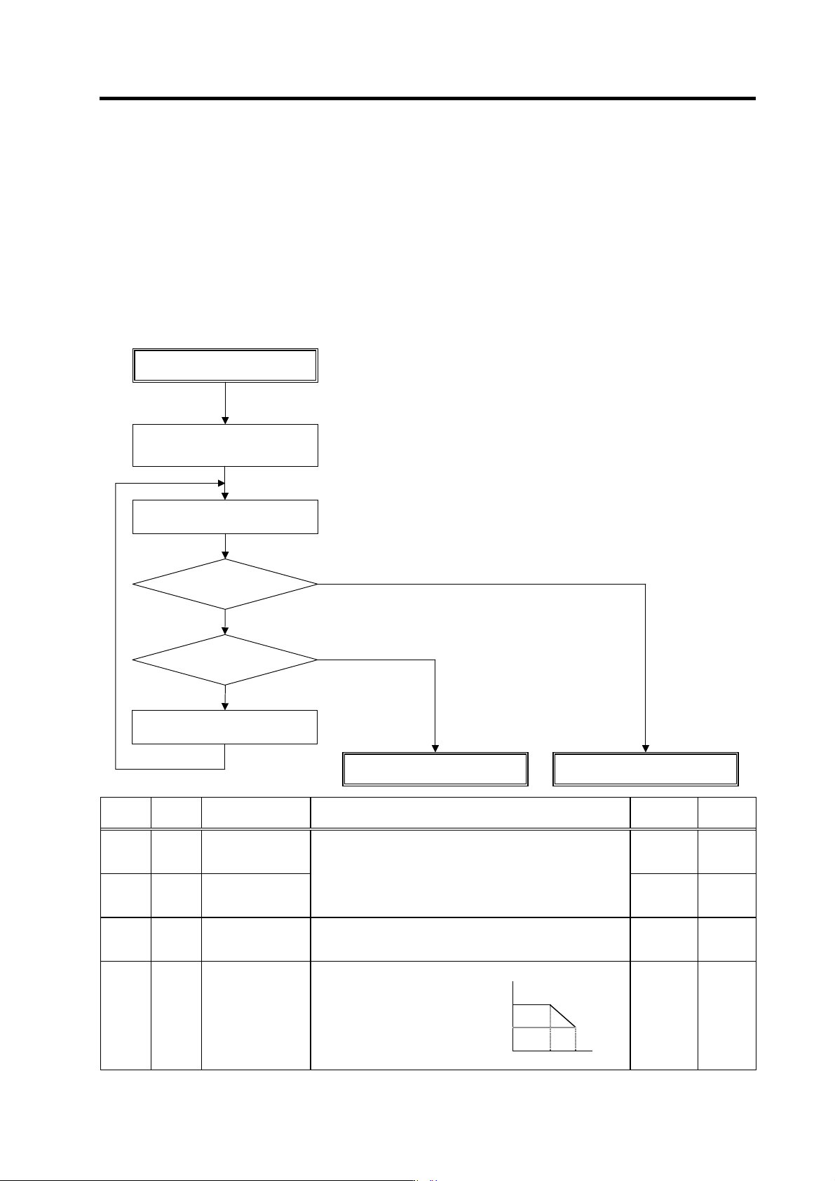
(6) Adjusting speed loop gain
The speed loop gain adjustment is made to improve the high-speed range characteristics for
speeds of 10,000r/min and higher. Use only the motor-specific standard settings for the basic
parameters SP022(VGNP1 ) and SP023 (VGNI1).
If the problems shown below occur during constant-speed operation at a speed of 10,000r/min or
higher, set and adjust the parameter SP065(VCGN1)and the parameter SP066(VCSN1).
1) A swell or spike ap pears in the current waveform
2) An overvoltage con dition (alarm 32) occurs
If the maximum speed is 10,000 r/min or less, or if no improvement is seen after adjusting the
speed loop gain, then adjust the current loop gain.
No. Abbr. Parameter name Details
Setting
range
Standard
SP022 VGNP1* Speed loop gain
proportional term
under speed control
0 to 1000 63
SP023 VGMI1* Speed loop gain
integral term under
speed control
Basically, use standard setting value set for each motor.
0 to 1000 60
SP065 VCGN1* Target value of
variable speed loop
proportional gain
Set the magnification of speed loop proportional gain with
respect to SP022 (VGNP1) at the maximum motor speed
defined in SP017 (TSP).
0 to 100
(%)
100
SP022
SP022×
(SP065/100)
SP066 VCSN1* Change starting
speed of variable
speed loop
proportional gain
Set the speed when the
speed loop proportional
gain change starts.
Set 10,000 normally.
0 SP066 SP017
0 to 32767
(r/min)
0
Adjusting SP065
Abnormal current waveform
alarm activated?
SP065 adjustment completed
Increase SP065 by –10.
YES
Measure acceleration/deceleration
waveform at high speed
SP065=30?
NO
Set SP065=100,
SP066=10000
YES
Adjust the current loop gain