MDS-C1-SPA Series INSTRUCTION MANUALib1500152(eng)a.pdf - 第186页
5. Troubleshooting 5 - 15 Alarm No. 62 Frequency error The input power frequency excee ded the specified range. Investigation details Investigation results Remedies The alarm occurs each time immediately after the power …
5. Troubleshooting
5 - 14
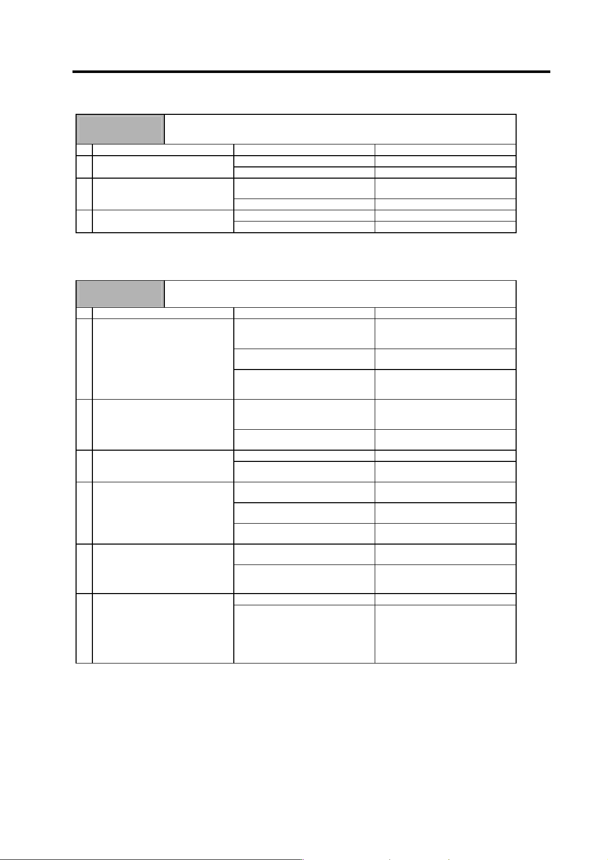
Alarm No.
5C
Orientation feedback error
After orientation was completed, the command and feedback error exceeded the parameter
setting.
Investigation details Investigation results Remedies
The cable is not correctly shielded. Shield the cable. 1 Check the PLG cable shield.
The cable is correctly shielded. Investigate item 2.
The cable is incorrectly connected or
broken.
Replace the cable. 2 Check the PLG cable connection.
Normal Investigate item 3.
There is a problem. Adjust the PLG output waveform. 3 Check the PLG output waveform.
Normal Replace the drive unit
The following alarms of the alarm No. 61 to 77 occur in the power supply unit.
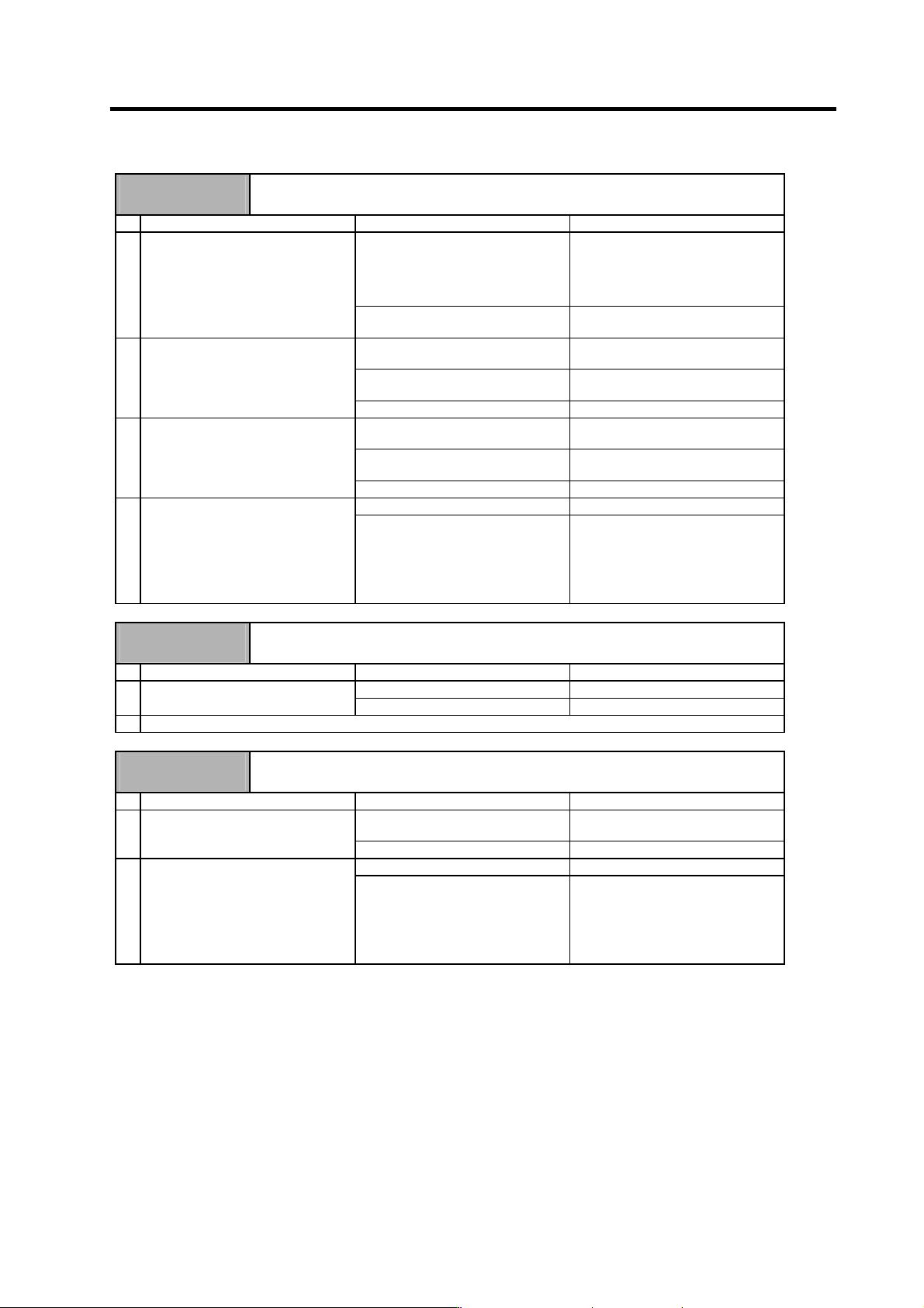
Alarm No.
61
Power module overcurrent
The power module's overcurrent protection function activated.
Investigation details Investigation results Remedies
The alarm occurs immediately after
200VAC is supplied and after READY
is turned ON.
Replace the unit.
The alarm occurs frequently during
READY ON.
Investigate item 3.
1 Check the state of the operation
when the alarm occurs, and check
the repeatability.
The alarm occurs after continuous
operation for a long time.
The unit is hot.
Investigate item 2.
The total load of all motors exceeds
the rated capacity of the power
supply unit.
Lower the motor load and operation
frequency.
2 Check the load state of all motors,
and the starting/stopping frequency.
The total does not exceed the
capacity.
Investigate item 3.
The power capacity is insufficient. Increase the power capacity. 3 Check the power capacity.
The specified power capacity is
secured.
Investigate item 4.
The voltage drops to 170V or less
occasionally.
Increase the power capacity.
The difference of the voltage across
wires is 10V or more.
Improve the power phase balance.
4 Measure the voltage across wires.
• Is the voltage 170V or more even
when the motor is accelerating?
The difference of the voltage across
wires is less than 10V.
Investigate item 5.
The power voltage is distorted. Improve the source of the distortion.
Install an AC reactor.
5 Measure the power voltage with a
synchroscope, and check whether
there is any distortion.
• Are there any other devices
causing the power distortion?
The power voltage waveform is not
abnormal.
Investigate item 6.
No abnormality is found in particular. Replace the unit. 6 Check if there is any abnormality in
the unit's ambient environment.
(Ex. Noise, grounding)
The grounding is incomplete.
An alarm will occur easily if another
device operates.
Take remedies according to the
causes of the abnormality.
Ex. Incomplete grounding:
Additionally ground.
Noise: Noise measures for
other devices.
5. Troubleshooting
5 - 15
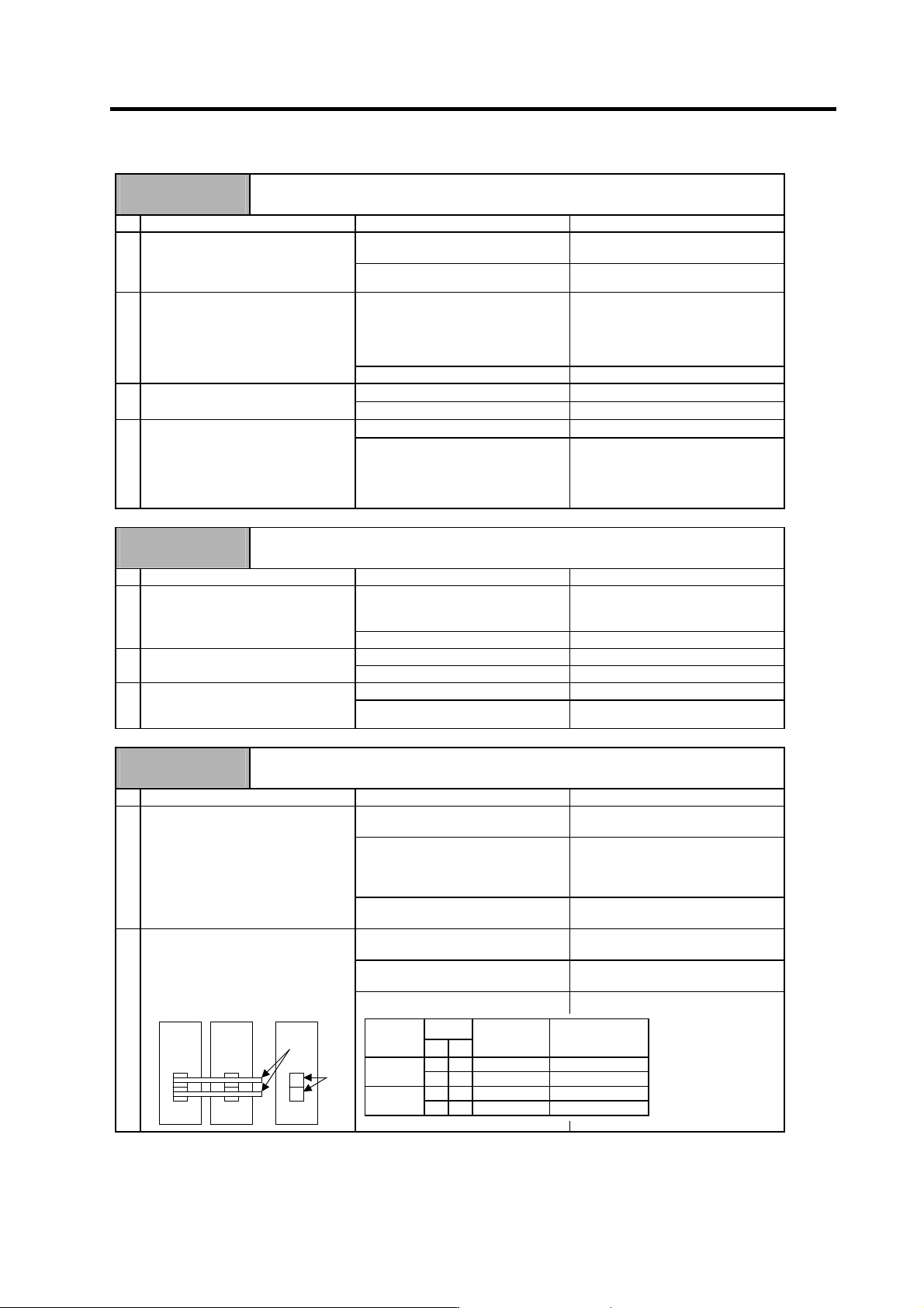
Alarm No.
62
Frequency error
The input power frequency exceeded the specified range.
Investigation details Investigation results Remedies
The alarm occurs each time
immediately after the power is turned
ON. Or, the alarm occurs
occasionally regardless of the
operation state.
Investigate item 2.
1 Check the state of the operation
when the alarm occurs, and check
the repeatability.
The alarm occurs only while the
motor is accelerating/decelerating.
Investigate item 3.
The frequency is deviated from
50Hz±3% or 60Hz±3%.
Review the power facilities.
The voltage waveform dips at some
sections.
Improve the source of the distortion.
Install an AC reactor.
2 Measure the power voltage waveform
during normal operation.
There is no problem. Investigate item 4.
The frequency greatly fluctuates
during acceleration/deceleration.
Review the power facilities.
The voltage waveform during
deceleration dips in some sections.
Improve the source of the distortion.
Install an AC reactor.
3 Measure the power voltage when the
motor is accelerating/decelerating.
There is no problem. Investigate item 4.
No abnormality is found in particular. Replace the unit. 4 Check if there is any abnormality in
the unit's ambient environment.
(Ex. Noise, grounding)
The grounding is incomplete.
An alarm will occur easily if another
device operates.
Take remedies according to the
causes of the abnormality.
Ex. Incomplete grounding:
Additionally ground.
Noise: Noise measures for
other devices.
Alarm No.
67
Phase failure
There is a phase failure in the input power.
Investigation details Investigation results Remedies
There are phases with no voltage. Correct the power supply. 1 Check the voltage for each input
phase.
There is no problem. Investigate item 2.
2 Check the alarm No. "71" items.
Alarm No.
68
Watch dog
The system is not operating normally.
Investigation details Investigation results Remedies
The alarm occurs each time READY
is turned ON.
Replace the unit. 1 Check the repeatability.
The alarm occurs occasionally. Investigate item 2.
No abnormality is found in particular. Replace the unit. 2 Check if there is any abnormality in
the unit's ambient environment.
(Ex. Noise, grounding)
The grounding is incomplete.
An alarm will occur easily if another
device operates.
Take remedies according to the
causes of the abnormality.
Ex. Incomplete grounding:
Additionally ground.
Noise: Noise measures for
other devices.
5. Troubleshooting
5 - 16
Alarm No.
69
Ground fault
The motor power cable is contacting FG (ground).
Investigation details Investigation results Remedies
100kΩ or less.
The motor or power cable may be
ground faulted.
1 Measure the insulation across the U,
V, W phase cables for all motors and
the ground. (Carry out a megger
test.)
100kΩ or more.
Investigate item 2.
Oil has come in contact. Take measures so that oil does not
come in contact. Check the motor's
cannon connector and the inside of
the terminal box, and clean as
necessary.
2 Has oil come in contact with the
motor or power cable?
Oil has not come in contact. Investigate item 3.
1MΩ or less.
Replace the motor or cable.
3 Measure the insulation again.
1MΩ or more.
Investigate item 2.
100kΩ or less.
Replace the drive unit.
4 Measure the resistance across the U,
V, W phase terminals of the
servo/spindle drive unit and the
ground.
(Do not measure the insulation, as
the unit could be damaged.)
100kΩ or more.
Replace the power supply unit.
Alarm No.
6A
External contactor melting
The external contactor's contact has melted.
Investigation details Investigation results Remedies
An alarm has occurred. Remove the cause of the alarm on
the drive side, and then carry out the
investigation details 2.
1 Check whether any alarm has
occurred on the drive unit side.
An alarm has not occurred. Investigate item 2.
The contactor has melted. Replace the contactor. 2 Check whether the contactor's
contact has melted.
The contactor has not melted. Investigate item 3.
The connection is correct. Correctly connect. 3 Check that the contactor excitation
wiring is correctly connected from the
power supply unit's MC1 terminal.
The connection is incorrect. Replace the power supply unit.
Alarm No.
6C
Main circuit error
An abnormality was detected in the main circuit capacitor's charging operation.
Investigation details Investigation results Remedies
The CHARGE lamp remains ON for
some time.
Replace the power supply unit.
The lamp turns ON instantly, but
when the alarm occurs and the
contactor turns OFF, the lamp turns
OFF immediately.
Investigate item 2.
1 Check the CHARGE lamp state when
the alarm occurs.
The lamp never turns ON. Investigate item 2.
Then replace the unit.
1) The power supply unit side is
abnormal.
Replace the power supply unit.
2) The drive unit side is abnormal. Disconnect the PN wiring, and then
check the drive unit side.
2 Disconnect the power supply unit's
PN terminal block wiring, and
measure the resistance value at 1)
and 2) shown below.
1) and 2) are both normal.
Replace the power supply unit.
Drive unit
Power supply
unit
P
N
2)
1)
Polarity
Tester
measure-
ment point
+-
Normal Abnormal
PN
Several 100Ω Short-circuit/∞Ω
1)
NP
∞Ω Several 100Ω
PN
Several 100Ω Short-circuit/∞Ω
2)
NP
∞Ω Several 100Ω