MDS-C1-SPA Series INSTRUCTION MANUALib1500152(eng)a.pdf - 第11页
CONTENTS 1. Installatio n 1-1 Inst allation of spindl e motor ............................................................................................. .... 1-2 1-1-1 Environmental conditions ........................…
CAUTION
(5) Troubleshooting
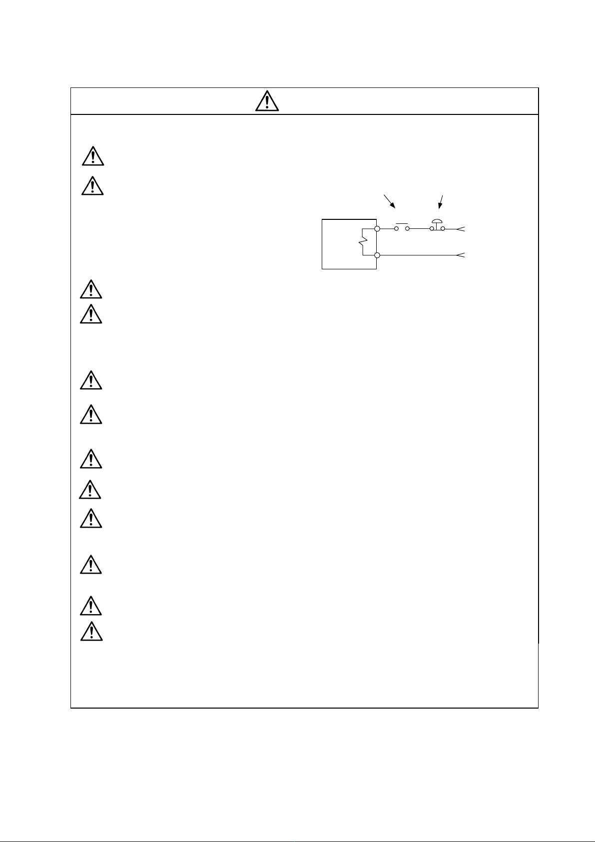
If a hazardous situation is predicted during power failure or product trouble, use a servomotor
with magnetic brakes or install an external brake mechanism.
Use a double circuit configuration
that allows the operation circuit for
the magnetic brakes to be operated
even by the external emergency
stop signal.
MBR
24VDC
EMG
Magnetic
brake
Servomotor
Shut off with the servomotor
brake control output.
Shut off with NC brake
control PLC output.
Always turn the input power OFF when an alarm occurs.
Never go near the machine after restorin g the power after a power failure, as the machine
could start suddenly. (Desi gn the machine so that personal safety can be ensu red even if the
machine starts suddenly.)
(6) Maintenance, inspection and part replacement
Always carry out maintenance and in spection after backing up the servo drive unit's prog rams
or parameters.
The capacity of the electrolytic capacitor will drop over time. To prevent secondary disasters
due to failures, replacing this part every five years when used under a normal environment is
recommended. Contact the Service Center or Service Station for replacement.
Do not perform a megger test (insulatio n resistance measurement) during inspection s.
If the battery low warning is issued, save the machining programs, tool data and parameters
with an input/output unit, and then replace the battery.
Do not short circuit, charge, overheat, incinerate or d isassemble the battery.
(7) Disposal
Treat this unit as general industrial waste . Note that MDS Series unit with a heat dissipating
fin protruding from the back of the unit contains substitute Freon. Do not dispose of this type
of unit as general industrial waste. Always return to the Service Center or Service Station.
Do not disassemble the servo drive unit or servomoto r parts.
Dispose of the battery according to local laws.
(8) General precautions
The drawings given in this Specifications and Maintenance Instruction Manual show the covers and
safety partitions, etc., removed to provide a clearer explanation. Always return the covers or partitions to
their respective places before starting operation, and always follow the instructions given in this manual.

CONTENTS
1. Installation
1-1 Installation of spindle motor ................................................................................................. 1-2
1-1-1 Environmental conditions .............................................................................................. 1-2
1-1-2 Shaft characteristics ...................................................................................................... 1-2
1-2 Installation of the control unit ............................................................................................... 1-3
1-2-1 Environmental conditions .............................................................................................. 1-3
1-2-2 Installation direction and clearance............................................................................... 1-4
1-2-3 Prevention of entering of foreign matter........................................................................ 1-4
1-2-4 Panel installation hole work drawings (Panel cut drawings)......................................... 1-5
1-2-5 Heating value ................................................................................................................. 1-6
1-2-6 Heat radiation countermeasures ................................................................................... 1-7
1-3 Installing the spindle detector .............................................................................................. 1-9
1-3-1 Magnetic sensor ............................................................................................................ 1-9
1-3-2 Spindle side detector ................................................................................................... 1-11
1-4 Noise measures ................................................................................................................. 1-12
2. Wiring and Connection
2-1 Connection diagram............................................................................................................. 2-3
2-1-1 Part system connection diagram...................................................................................... 2-3
2-1-2 Detailed connection diagram ........................................................................................... 2-4
2-2 Main circuit terminal block/control circuit connector............................................................ 2-7
2-2-1 Names and applications of main circuit terminal block signals and control circuit
connectors ..................................................................................................................... 2-7
2-2-2 Connector pin assignment............................................................................................. 2-8
2-3 Drive unit connection ..................................................................................................... .... 2-11
2-4 Motor and detector connection .......................................................................................... 2-14
2-4-1 Connection of the spindle motor.................................................................................. 2-14
2-5 Connection of power supply .............................................................................................. 2-17
2-5-1 Power supply input connection ...................................................................................... 2-17
2-5-2 Connecting the grounding cable.................................................................................. 2-20
2-5-3 Main circuit control ......................................................................................................... 2-21
2-6 Peripheral control wiring .................................................................................................... 2-23
2-6-1 Input interface .............................................................................................................. 2-23
2-6-2 Output interface ........................................................................................................... 2-25
2-6-3 Spindle coil changeover .............................................................................................. 2-27
2-6-4 Wiring of an external emergency stop......................................................................... 2-30
3. Setup
3-1 Initial setup ........................................................................................................................... 3-2
3-1-1 Setting the rotary switch ................................................................................................3-2
3-1-2 Transition of LED display after power is turned ON...................................................... 3-3
3-2 Setting the initial parameters for the spindle drive unit ....................................................... 3-4
3-2-1 Parameter setting method ............................................................................................. 3-4
3-2-2 List of spindle parameters ............................................................................................. 3-6
3-3 Initial adjustment of the spindle PLG................................................................................. 3-26
3-3-1 Adjusting the PLG installation...................................................................................... 3-26

4. Spindle Adjustment
4-1 D/A output specifications for spindle drive unit ................................................................... 4-2
4-1-1 D/A output specifications ............................................................................................... 4-2
4-1-2 Setting the output data ..................................................................................................4-2
4-1-3 Setting the output magnification .................................................................................... 4-3
4-2 Spindle control signal........................................................................................................... 4-5
4-2-1 Spindle control input (NC to SP) ................................................................................... 4-5
4-2-2 Spindle control output (SP to NC) ............................................................................... 4-15
4-3 Adjustment procedures for each control ........................................................................... 4-27
4-3-1 Basic adjustments........................................................................................................ 4-27
4-3-2 Adjusting the acceleration/deceleration operation ...................................................... 4-30
4-3-3 Adjusting the orientation control .................................................................................. 4-39
4-3-4 Adjusting the multi-point indexing orientation control.................................................. 4-55
4-3-5 Adjusting S-analog high-speed tapping control .......................................................... 4-64
4-3-6 Adjusting coil changeover............................................................................................ 4-69
5. Troubleshooting
5-1 Points of caution and confirmation ...................................................................................... 5-2
5-1-1 LED display when alarm or warning occurs.................................................................. 5-3
5-2 Protective functions list of units ........................................................................................... 5-4
5-2-1 List of alarms.................................................................................................................. 5-4
5-2-2 List of warnings .............................................................................................................. 5-6
5-3 Troubleshooting ................................................................................................................... 5-7
5-3-1 Troubleshooting at power ON ....................................................................................... 5-7
5-3-2 Troubleshooting for each alarm No. .............................................................................. 5-8
5-3-3 Troubleshooting for each warning No. ........................................................................ 5-21
5-3-4 Troubleshooting the spindle system when there is no alarm or warning ................... 5-22
6. Maint enan ce
6-1 Inspections ........................................................................................................................... 6-2
6-2 Service parts ........................................................................................................................ 6-2
6-3 Adding and replacing units and parts .................................................................................. 6-3
6-3-1 Replacing the drive unit .................................................................................................6-3
6-3-2 Replacing the unit fan .................................................................................................... 6-4
Appendix 1. Cable and Connector Specifications
Appendix 1-1 Selection of cable .............................................................................................. A1-2
Appendix 1-1-1 Cable wire and assembly ............................................................................ A1-2
Appendix 1-2 Cable connection diagram................................................................................. A1-4
Appendix 1-3 Connector outline dimension drawings ............................................................. A1-8
Appendix 2. Compliance to EC Directives
Appendix 2-1 Compliance to EC Directives ............................................................................ A2-2
Appendix 2-1-1 European EC Directives.............................................................................. A2-2
Appendix 2-1-2 Cautions for EC Directive compliance ........................................................ A2-2