MDS-C1-SPA Series INSTRUCTION MANUALib1500152(eng)a.pdf - 第146页
4. Spindle Adjustment 4 - 55 4-3-4 Adjusting the multi-point indexing orientation control This control is valid only for the encoder orientation or motor PLG orientation spe cifications. (1) Necessary input/output I/O Si…

4. Spindle Adjustment
4 - 54
[6] The orientation complete signal is not ou tput
Cause Investigation item Remedy Remarks
1
Parameter setting
values are incorrect
Orientation complete is not set to the
general-purpose output. Or, the input
in which the actual orientation
complete is wired and the location set
in the parameter are different.
Set “1” in any one of the
general-purpose outputs SP141 to
SP154 which corresponds to the
output section where the
orientation complete has been
wired.
2 The machine's load is
heavy
The in-position parameter SP004
(OINP) is too small.
Review the in-position range, and
increase SP004 (OINP).
State is improved if delay
compensation control is stopped
during orientation stopping.
(State is improved when changed to
PI control).
Review the values set for the
speed loop gain for orientation
parameters SP098 (VGOP),
SP099 (VGOI) and SP100
(VGOD).
3 Carry out the items for [1] Orientation does not take place (motor keeps rotating).
4. Spindle Adjustment
4 - 55
4-3-4 Adjusting the multi-point indexing orientation control
This control is valid only for the encoder orientation or motor PLG orientation specifications.
(1) Necessary input/output
I/O Signal name I/O mode
Encoder
orientation
Motor PLG
orientation
Orientation start command (ORC) General-purpose input
Indexing forward run command, indexing
reverse run command (WRN, WRI)
General-purpose input
Stop position command data (R1 to R12) Dedicated input
Gear selection command 1, 2 (GR1, GR2) General-purpose input
Input
Torque limit input 1 to 3 (TL1 to TL3) General-purpose input
Orientation completed (ORCA) General-purpose output
Output
Index positioning completed (WRCF) General-purpose output
: Mandatory : Set as required
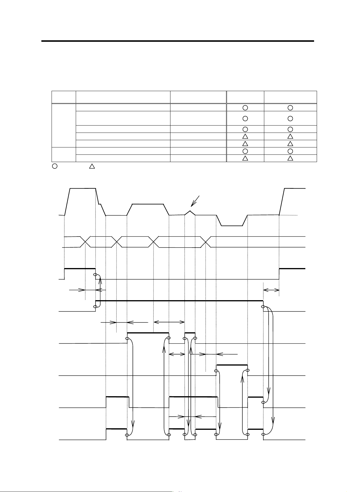
(2) Operation sequence
Stop
position
command
data
0
Forward
run
signal
t4
ON
OFF
ON
OFF
t1
t2
t2
t2
When the indexing angle is within
the in-position range
t3
t5
Motor
speed
Orientation
start
Forward run
indexing
Reverse run
indexing
Orientation
completed
Index
positioning
completed
OFF
OFF
OFF
ON
ON
ON
ON ON
ON
ON
OFF
ON
ON ONON
OFF
OFFOFF
OFF
OFFOFF
OFF
OFF
OFF
t1 to t4: 20ms ore more t5: 200ms (Standard value)

4. Spindle Adjustment
4 - 56
[Outline of operation]
After having the motor stop with the orientation stop, change the stop position comman d data while the
orientation command is ON. When the forward (reverse) run indexing signal is turned ON, the motor
starts running again and stops at the target stop position within one rotation.
Note that once the orientation command has been turned OFF, it must be turned ON again to make an
orientation stop; otherwise, indexing operation cannot be carried out.
CAUTION
1. Stop position command dat a (R1 to R12) is read at the rising edge of the
forward (reverse) run indexing signal. Thus even if the stop position
command data is changed during indexing operation, the angle will not be
read until the next forward (reverse) run indexing signal turns ON.
2. When mechanically clamping the spi ndle motor while the orient ation
command is being turned ON, execute a torque limit during clamping by
turning the torque limit input (TL1 to TL3) ON.
3. Once the forward/reverse run indexing signal has been turned ON, even if
the motor is attempted to be turned OFF in the middle of indexing
operation, the motor keep s running until i t s operation is completed. Turn the
orientation co mmand or machine ready completion input OFF to stop the
motor. The m otor is in an uncontrolled state (free run) at this time.
4. The forward/reverse run indexing signal can be turned OFF after outputting
the indexing completion signal a s sh own above, or it can b e turned OFF by
using a timer af ter inputting. In the latter case, the timer must be no shorter
than 50ms.
5. When executing indexing operations, large torque L-gear is used for the
machine with gear step s, and low-speed coil is used for the coil-ch angeover
motor. In this case, shif t the machine gear and gear selection command to
the L-gear before inputting the orientation command. After that, do not
change until turning the orientation start command OFF.
6. The accuracy and least movement increment of indexing may not satisfy
the specifications due to the machine backlash, inertia and friction torque.
In the case with built-in motor, this may be attributed to the PLG adjustment
value, etc., as well.
In order to secure stable accuracy, especially the following two points must
be observed.
(1) Load inertia shall b e less than 3-times the amount of motor inertia.
(2) Friction torque shall be less than 30% of the motor rating.