MDS-C1-SPA Series INSTRUCTION MANUALib1500152(eng)a.pdf - 第165页
4. Spindle Adjustment 4 - 74 (Reference) The generation of the signals in item [1] and [2] are shown in the followin g flow chart. ST ART ZS:ON ? LCS:ON ? SD:ON ? LCS=ON LCS=OFF S peed command ≦ N2 ? S peed command ≦ N2 …
4. Spindle Adjustment
4 - 73
2) Changing the coil during spindle motor rotation
This method uses the characteristics of coil changeover to change the coil during motor rotation,
and changing directly from the low-speed coil to the high-speed coil. The transition time is shorter
compared to the method explained in the previous section. The speed detection signal (SD) is
used with this method, and the L coil selection command signal (LCS) is input in the following
manner.
[1] To accelerate from a stopped state (To accelerate after zero speed output signal turns ON)
(i) First, judge the high-speed/low-speed coil range with the speed command, and select the
coil. (Input the L coil selection command signal (LCS).)
(ii) Next, turn the start signal ON and accelerate the motor.
(iii) Hold the L coil selection command signal (L CS) in the state of (i).
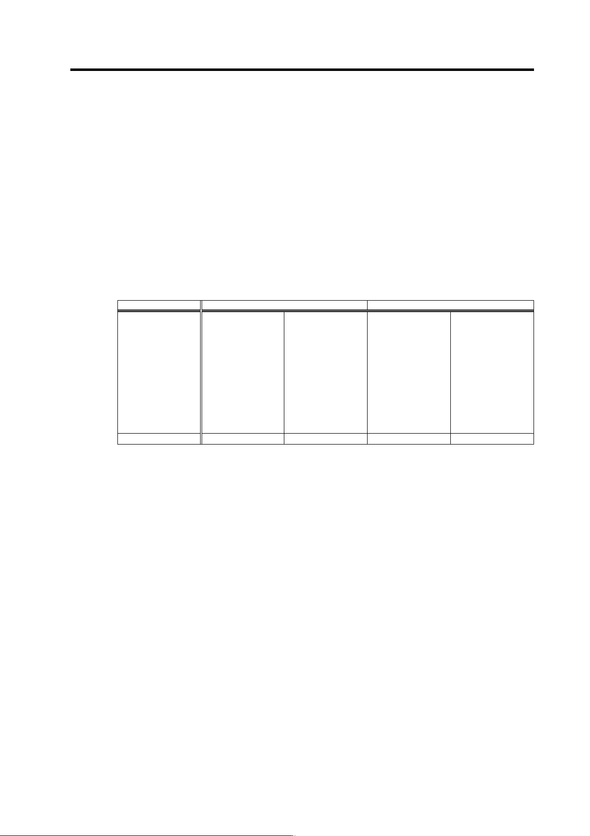
[2] When varying the speed, turn the L coil selection command signal (LCS) ON and OFF as
shown in the following table.
Current coil state When low-speed coil is selected When high-speed coil is selected
Next speed
command
Low-speed coil
range
Does not change
(LCS: ON)
High-speed coil
range
Judge state of SD
signal
[1] SD: ON
→LCS: ON
[2] SD: OFF
→LCS: OFF
Low-speed coil
range
Judge state of SD
signal
[1]SD: ON
→LCS: ON
[2] SD: OFF
→LCS: OFF
High-speed coil
range
Does not change
(LCS: OFF)
Operation mode
[2]-A [2]-B [2]-C [2]-D
(Note) The conditions in item 1) are applied to prevent the contactor from turning ON/OFF needlessly during
acceleration/deceleration.
Since the speed detection signal (SD) has a hysteresis, the conditions in item 2) are applied to prevent the
contactor from turning ON/OFF needlessly (inconsistently) when operating near the coil change speed and
continuously varying the speed.
4. Spindle Adjustment
4 - 74
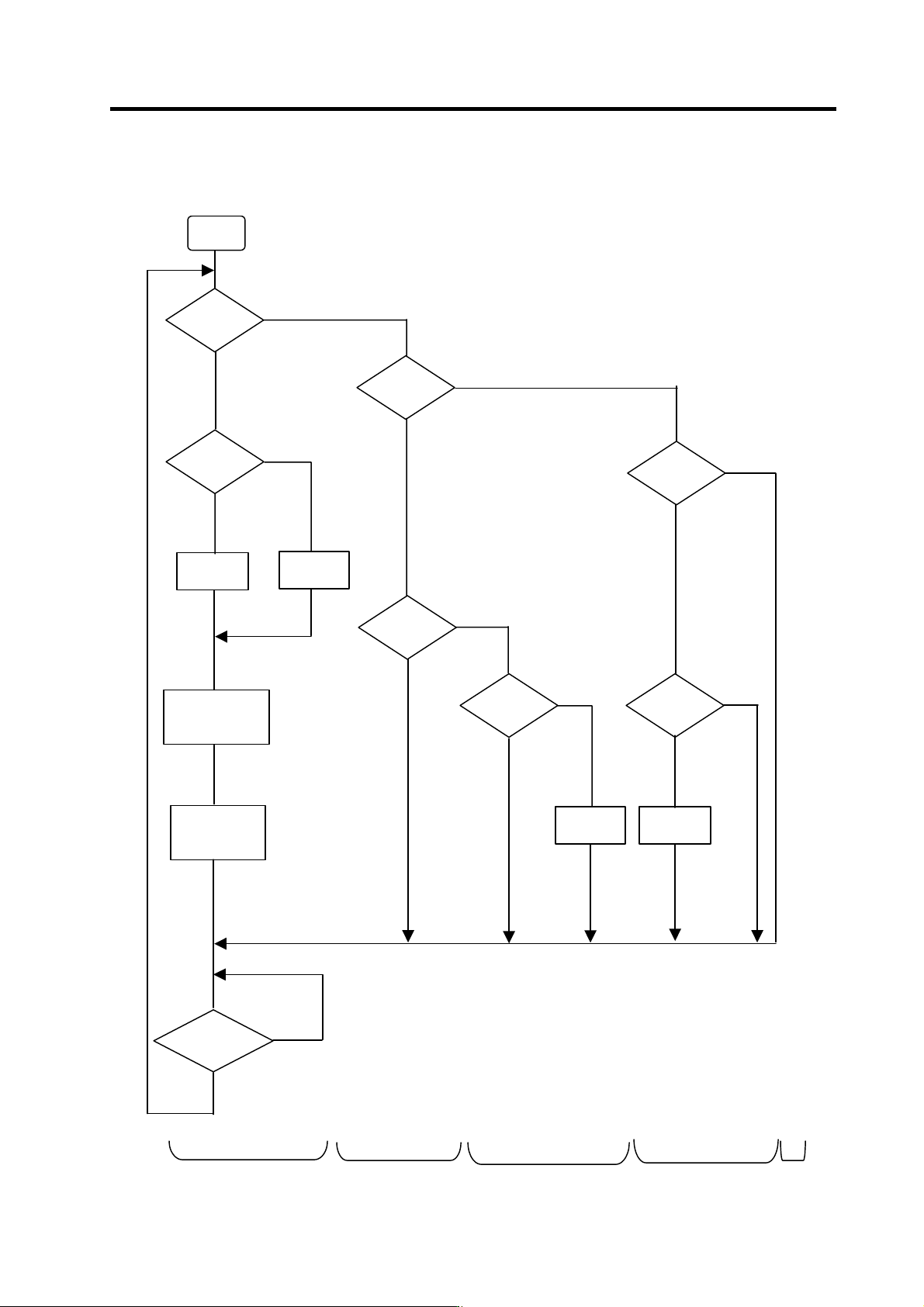
(Reference) The generation of the signals in item [1] and [2] are shown in the following flow chart.
START
ZS:ON ?
LCS:ON ?
SD:ON ?
LCS=ON
LCS=OFF
Speed
command
≦N2 ?
Speed
command
≦N2 ?
LCS=OFF
LCS=ON
Speed
command
≦N2 ?
SD:ON ?
Check TM timer
or coil changed
signal
SRN/SRI
:ON
Was speed
command changed?
NO
YES
YES
(Low-speed
coil range
command)
NO
(High-speed coil range command)
YES
(Low-speed
coil range)
NO
(High-speed
coil range)
NO
(High-speed
coil range)
YES
(Low-speed
coil range)
NO
YES
(Low-speed coil
range command)
NO
(High-speed coil selected)
YES
(Low-speed coil selected)
NO
YES
NO
YES
(Operation mode) [1] [2] - A [2] - B [2] - D[2] - C
4. Spindle Adjustment
4 - 75
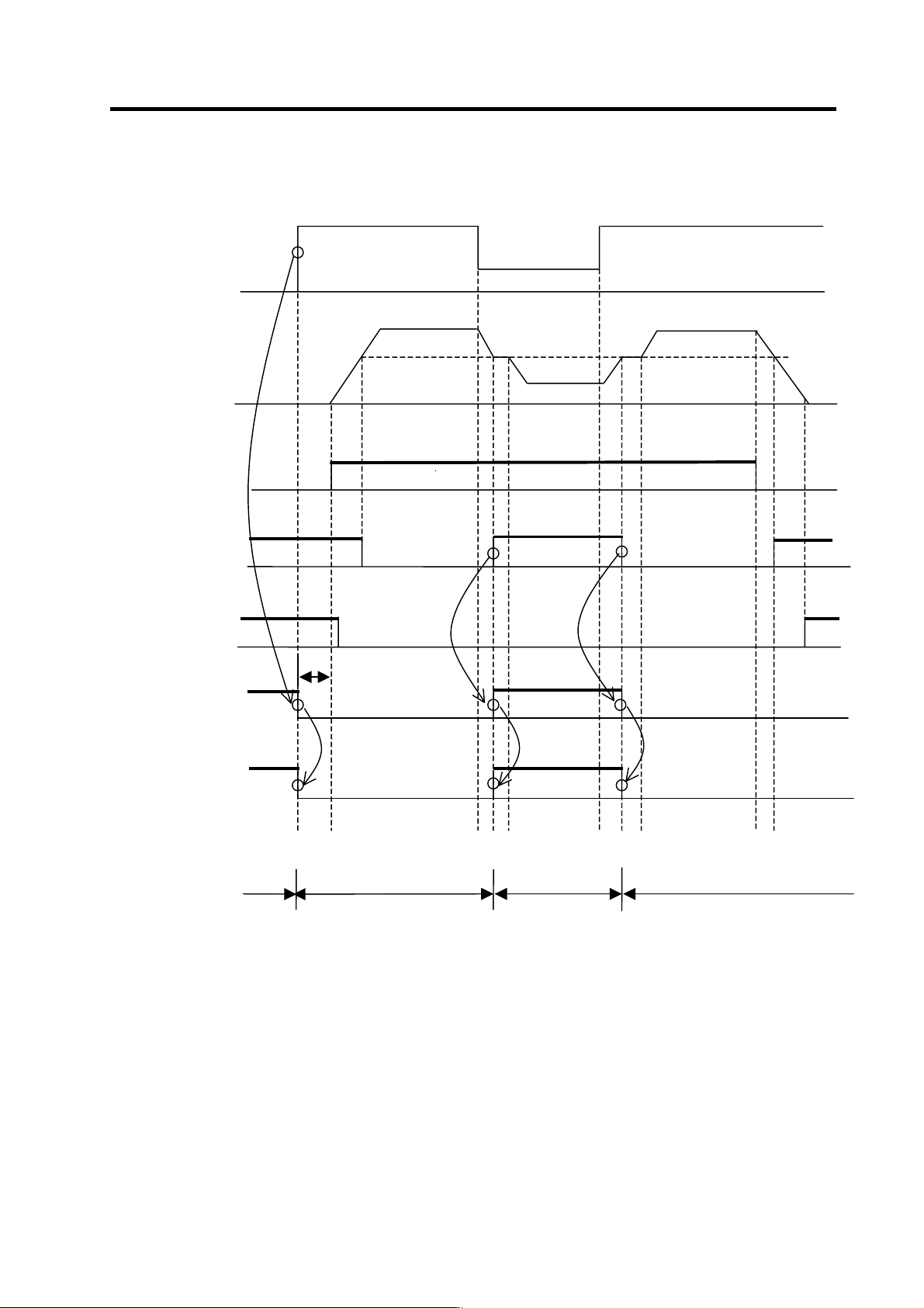
<0 → N3 → N1 → N3 → 0 changeover sequence>
Speed command
Motor rotation speed
Start signal
(SRN or SRI)
Speed detection signal
(SD)
Zero speed signal
(ZS)
L coil selection
command signal
(LCS)
L coil selected signal
(LCSA)
t1
N3
N1
N3
N2
N3
N1
N3
ON
ON
ON
ON
ON
ON
ON
ON
ON
ON
(Note)
High-speed coil selection Low-speed coil selection High-speed coil selection
t2
t3 t4 t5
t6 t7 t8
t9 t10
[1] When the speed command reaches N3 (high-speed coil range) at t1, the system confirms that
the zero speed signal (ZS) is ON, and then turns the L coil selection command signal (LCS)
OFF (high-speed coil selection). Then, t he start signal (SRN or SRI) is turned O N at t2, and the
motor accelerates.
[2] Next when the speed command is changed to N1 (low-speed coil range) at t3, the motor starts
decelerating toward N1. However, when it reaches the coil changeover speed N2 at t4, the
speed detection signal (SD) changes from OFF to ON. The system confirms that this speed
detection signal (SD) has turned ON, and then changes the L coil selection command signal
(LCS) from OFF (High-speed coil selection) to ON (low-speed coil selection). This changes the
coil, and when completed (t5), the motor continues to decelerate to N1.