MDS-C1-SPA Series INSTRUCTION MANUALib1500152(eng)a.pdf - 第102页
4. Spindle Adjustment 4 - 11 bit1. Speed selection 1 (ss1) bit2. Speed selection 2 (ss2) bit3. Speed selection 3 (ss3) This is used to determine the speed command with three inputs. By using the combination of ss1 to 3 i…
4. Spindle Adjustment
4 - 10
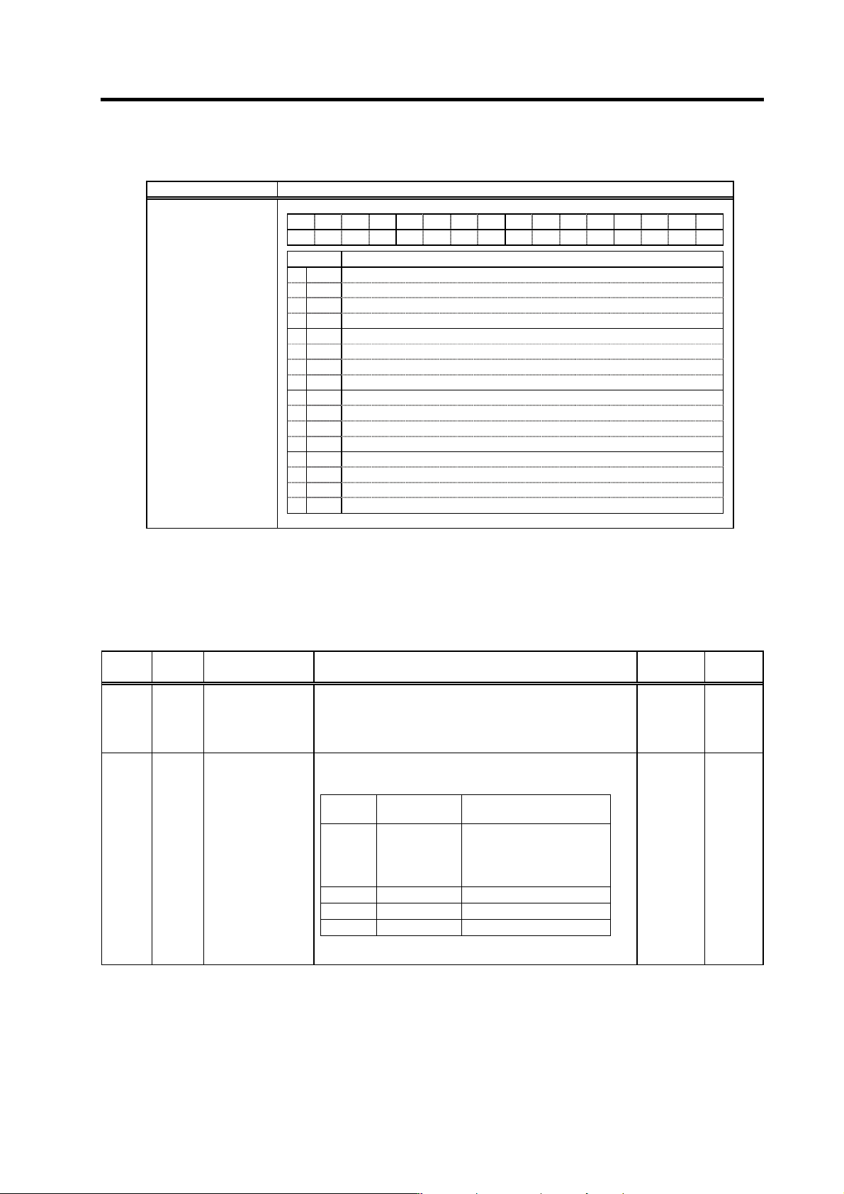
(4) Spindle control input 4
Name Details
F E D C B A 9 8 7 6 5 4 3 2 1 0
hsp ovr deg
ss3 ss2 ss1 Emg
bit Details
0 Emg Emergency stop
1 ss1 Speed selection1
2 ss2 Speed selection2
3 ss3 Speed selection3
4
5 deg Digital speed command valid
6 ovr Override input
7 hsp S-analog speed synchronous tapping
8
9
A
B
C
D
E
F
Spindle control input 4
bit0. Emergency stop (Emg)
This signal turns ON when the emergency stop input signal is opened (OFF). When this signal is
opened (OFF) during motor rotation, the motor will decelerate to stop.
Related spindle parameters
No. Abbr. Parameter name Details
Setting
range
Standard
SP129
to
SP140
HI01
to
HI12
General-purpose
input selection 1
to
General-purpose
input selection 12
Set the following value in any one of these parameters when
using the emergency stop.
"10": Emergency stop (emg) 0 to 21 0
SP192 FNC0
Function selection at
emergency stop
Set the state of alarm output and ready-ON output at the
emergency stop.
Setting
value
Alarm output Ready-ON output
0 Not available Turned OFF when the
amount of time set in
SP055(SETM) has passed
after the motor stopped
1 Available Same as above
2 Not available Continued ON
3 Available Continued ON
Note) When the ready-ON input signal is turned OFF, the
ready-ON signal is turned OFF regardless of the settings above.
0 to 1000 0
4. Spindle Adjustment
4 - 11
bit1. Speed selection 1 (ss1)
bit2. Speed selection 2 (ss2)
bit3. Speed selection 3 (ss3)
This is used to determine the speed command with three inputs.
By using the combination of ss1 to 3 input, set the speed command value to the value set in SP162
to SP169.
Note that, however, if the value of SP162 is "0" and ss1 to 3 are all OFF, the speed command is
the input given by the regular analog voltage.
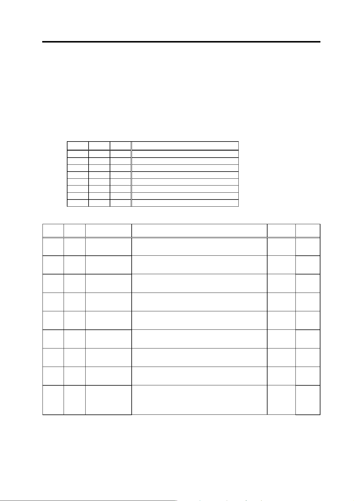
ss3 ss2 ss1 Speed setting value
0 0 0 SP162
0 0 1 SP163
0 1 0 SP164
0 1 1 SP165
1 0 0 SP166
1 0 1 SP167
1 1 0 SP168
1 1 1 SP169
Related spindle parameters
No. Abbr. Parameter name Details
Setting
range
Standard
SP162 SS00 Speed setting 0
Regardless of whether the speed command mode is analog or
digital, the motor is run by the value set here when the
forward/reverse run signal is input.
0 to 32767
(r/min)
0
SP163 SS01 Speed setting 1
Set the motor speed command value when the speed selection
1 is assigned to the general-purpose input and the input is
turned ON.
0 to 32767
(r/min)
0
SP164 SS02 Speed setting 2
Set the motor speed command value when the sp eed selection
1, 2 or 1, 2, 3 are assigned to the general-purpose input and
only the speed selection 2 is turned ON.
0 to 32767
(r/min)
0
SP165 SS03 Speed setting 3
Set the motor speed command value when the speed selection
1, 2 or 1,2,3 are assigned to the general-pu rpose input and the
speed selection 1,2 are turned ON.
0 to 32767
(r/min)
0
SP166 SS04 Speed setting 4
Set the motor speed command value when the speed selection
1,2,3 are assigned to the general-purpose input and the speed
selection 3 is turned ON.
0 to 32767
(r/min)
0
SP167 SS05 Speed setting 5
Set the motor speed command value when the speed selection
1,2,3 are assigned to the general-purpose input and the speed
selection 1,3 are turned ON.
0 to 32767
(r/min)
0
SP168 SS06 Speed setting 6
Set the motor speed command value when the speed command
1,2,3 are assigned to the general-purpose input and the speed
selection 2,3 are turned ON.
0 to 32767
(r/min)
0
SP169 SS07
Speed setting 7
Set the motor speed command value when the speed selection
1,2,3 are assigned to the general-purpose input and the speed
selection 1,2,3 are all turned ON.
0 to 32767
(r/min)
0
SP129
to
SP140
HI01
to
HI12
General-purpose
input selection 1
to
General-purpose
input selection 12
Set the following value in any one of these parameters when
using the speed selection.
"11": Speed selection 1 (ss1)
"12": Speed selection 2 (ss2)
"13": Speed selection 3 (ss3)
0 to 21 0
4. Spindle Adjustment
4 - 12
bit5. Digital speed command input valid (deg)
This signal turns ON when the digital speed command input is closed (ON). When this signal is
turned ON, the speed command is determined by the external input R01(CN12-1 pin) to
R12(CN12-16 pin) 12bit. The com mon is CES2(CN12-19 pin).
The types of digital speed command include the followings, and one of them can be selected (by
the parameter).
1) BCD code 2 digits: 8bit
2) BCD code 3 digits: 12bit
3) Binary (12-bit binary): 12bit
4) Signed binary: 12bit
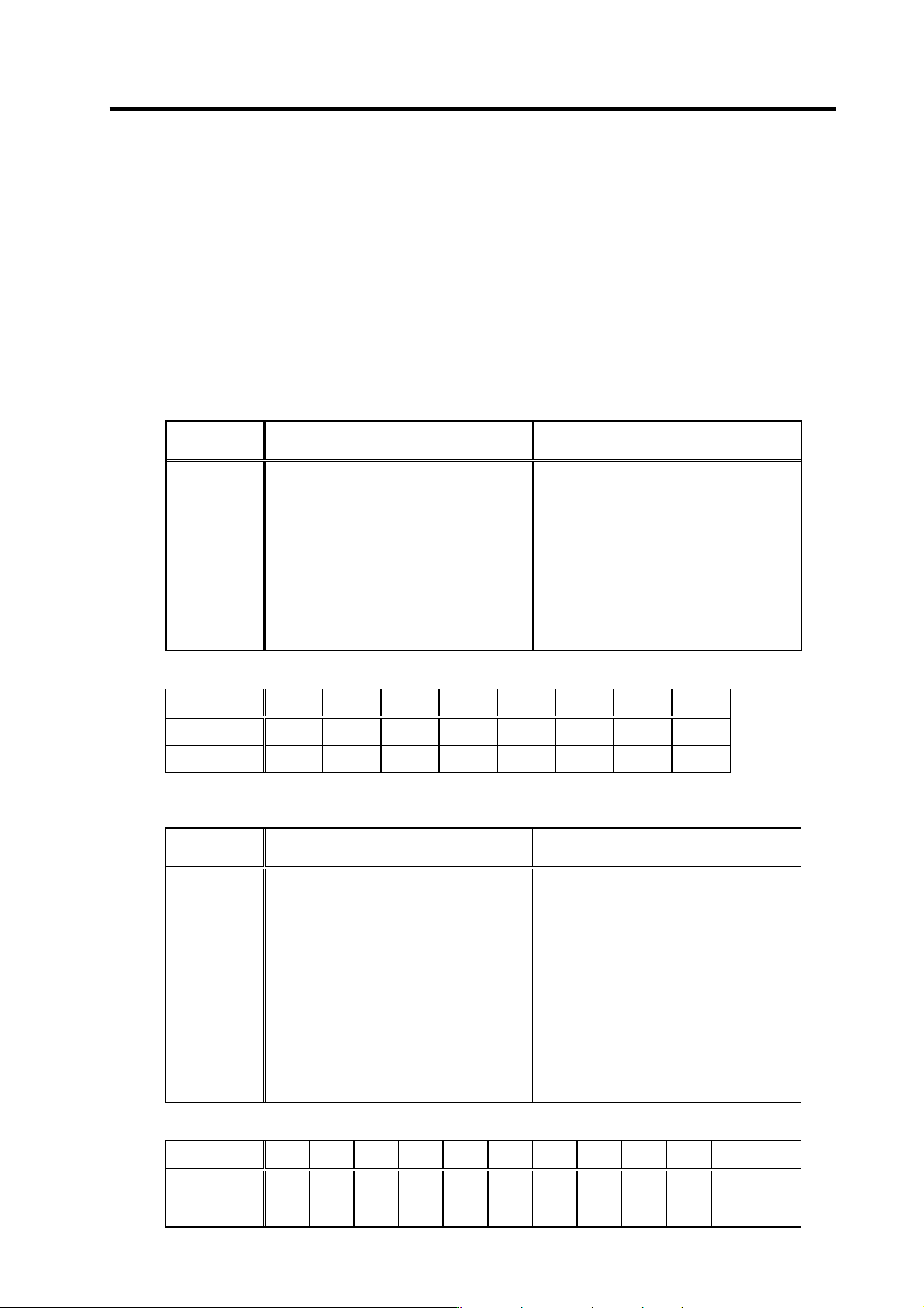
1) BCD code 2 digits
Rotation speed in respect to comma nd value is as shown below.
BCD code
Motor rotation speed
(When the max. speed is 10000r/min)
Motor rotation speed
(When the max. speed is 6000r/min)
00
01
02
•
•
•
•
•
98
99
0r/min
101r/min
202r/min
•
•
•
•
•
9898r/min
10000r/min
0r/min
60r/min
121r/min
•
•
•
•
•
5939r/min
6000r/min
(Example) Input method is as shown below. ("1"=Co ntact ON(closed), "0"=Contact OFF(open))
BCD code R08 R07 R06 R05 R04 R03 R02 R01
01 0 0 0 0 0 0 0 1
99 1 0 0 1 1 0 0 1
2) BCD code 3 digits
Rotation speed in respect to comma nd value is as shown below.
BCD code
Motor rotation speed
(When the max. speed is 10000r/min)
Motor rotation speed
(When the max. speed is 6000r/min)
000
001
002
•
•
•
•
•
998
999
0r/min
10r/min
20r/min
•
•
•
•
•
9989r/min
10000r/min
0r/min
6r/min
12r/min
•
•
•
•
•
5993r/min
6000r/min
(Example) Input method is as shown below. ("1"=Co ntact ON(closed), "0"=Contact OFF(open))
BCD code R12 R11 R10 R09 R08 R07 R06 R05 R04 R03 R02 R01
001 0 0 0 0 0 0 0 0 0 0 0 1
999 1 0 0 1 1 0 0 1 1 0 0 1