MDS-C1-SPA Series INSTRUCTION MANUALib1500152(eng)a.pdf - 第209页
Appendix 2. Compliance to EC Directives A2 - 2 Appendix 2-1 Compliance to EC Directives Appendix 2-1-1 European EC Directives In the EU Community, the attachment of a CE mark (C E marking) is mandatory to indicate that t…

A2 - 1
Appendix 2. Compliance to EC Directives
Appendix 2-1 Compliance to EC Directives ...........................................................................................A2-2
Appendix 2-1-1 European EC Directives............................................................................................A2-2
Appendix 2-1-2 Cautions for EC Directive compliance ......................................................................A2-2
Appendix 2. Compliance to EC Directives
A2 - 2
Appendix 2-1 Compliance to EC Directives
Appendix 2-1-1 European EC Directives
In the EU Community, the attachment of a CE mark (CE marking) is mandatory to indicate that the basic
safety conditions of the Machine Directives (issued Jan. 1995), EMC Directives (issued Jan. 1996) and
the Low-voltage Directives (issued Jan. 1997) are satisfied. The machines and devices in which the
servo and spindle drive are assembled are the targets for CE marking.
(1) Compliance to EMC Directives
The servo and spindle drive are components designed to be used in combination with a machine or
device. These are not directly targeted by the Directives, but a CE mark must be attached to
machines and devices in which these components are assembled. The next section "EMC
Installation Guidelines", which explains the unit installation and control panel manufacturing
method, etc., has been prepared to make compliance to the EMC Directives easier.
(2) Compliance to Low-voltage Directives
The MDS-C1-SPA Series units are targeted for the Low-voltage Directives. An excerpt of the
precautions given in this specification is given below. Please read this section thoroughly before
starting use.
A Self-Declaration Document has been prepared for the EMC Directives and Low-voltage
Directives. Contact Mitsubishi or your dealer when required.
Appendix 2-1-2 Cautions for EC Directive compliance
Use the Low-voltage Directive compatible parts for the servo/spindle drive and servo/spindle motor. In
addition to the items described in this instruction manual, observe the items described below.
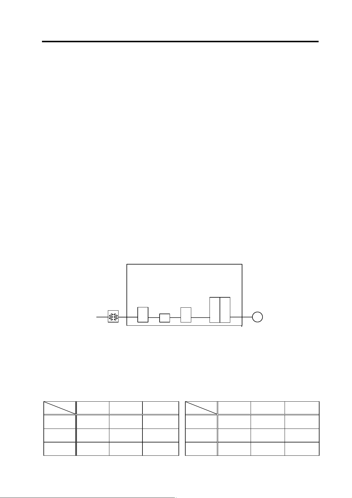
(1) Configuration
Use a type B (AC/DC detectable type) breaker
Isolating
transformer
Circuit breaker
AC reactor
Electromagnetic
contactor
Drive unit
CB
MC
M
(2) Environment
Use the units under an Overvoltage Category II and Pollution Class of 2 or less environment as
stipulated in IEC60664.
These units do not provide protection against electric shock and fire sufficient for the requirements
of the Low-voltage Directive and relevant European standards by themselves, so provide additional
protection (refer to 5.2.4 and 7.1.6.1 of EN50178)
Drive unit Motor
During
operation
Storage
During
transportation
During
operation
Storage
During
transportation
Ambient
temperature
0°C to 55°C -15°C to 70°C -15°C to 70°C
Ambient
temperature
0°C to 40°C -15°C to 70°C -15°C to 70°C
Humidity
90%RH or
less
90%RH or
less
90%RH or less Humidity
80%RH or
less
90%RH or
less
90%RH or
less
Altitude
1000m or
less
1000m or
less
13000m or
less
Altitude
1000m or
less
1000m or
less
13000m or
less
Appendix 2. Compliance to EC Directives
A2 - 3
(3) Power supply
[1] Use the power supply and servo/spindle drive unit under an Overvoltage Category II as
stipulated in IEC60664.
[2] In case of Overvoltage Category III, connect the PE terminal of the units to the earthed-neutral
of the star-connection power supply system.
[3] Do not omit the circuit breaker and electromagnetic contactor.
(4) Earthing
[1] To prevent electric shocks, always connect the servo/spindle drive unit protective earth (PE)
terminal (terminal with
mark) to the protective earth (PE) on the control panel.
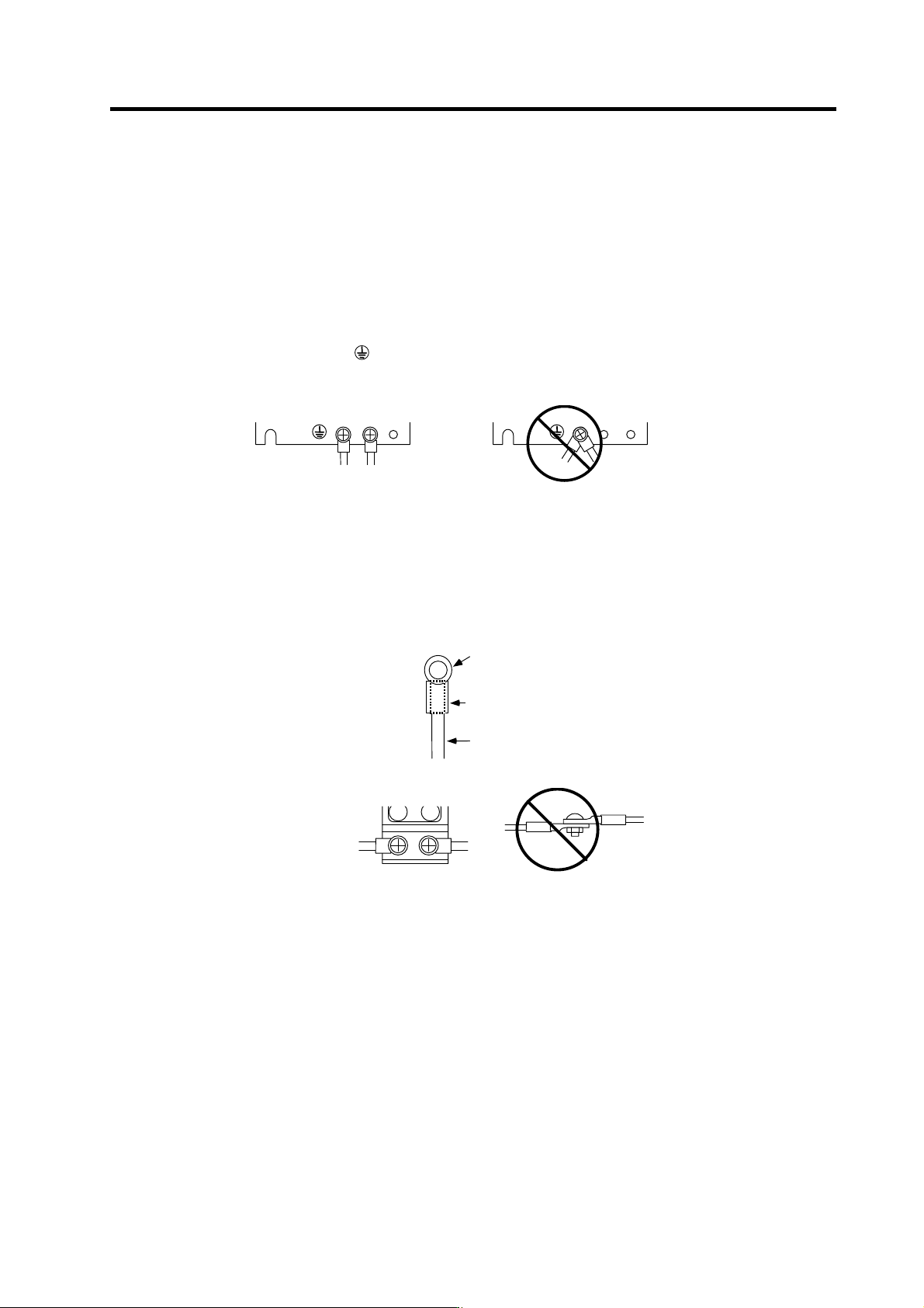
[2] When connecting the earthing wire to the protective earth (PE) terminal, do not tighten the
wire terminals together. Always connect one wire to one terminal.
PE terminal
PE terminal
[3] Select the earthing wire size in accordance with Table 1 of EN60204-1.
(5) Wiring
[1] Always use crimp terminals with insulation tubes so that the connected wire does not contact
the neighboring terminals.
Crim p termi nal
Insul ation tube
Wire
[2] Do not connect the wires directly.
[3] Select the size of the wires for input power supply to Power Supply unit in accordance with
Table 4 and 5 of EN60204-1.