MDS-C1-SPA Series INSTRUCTION MANUALib1500152(eng)a.pdf - 第219页
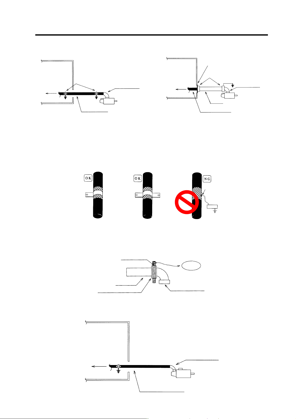
Appendix 3. EMC Installation Guidelines A3 - 8 Appendix 3-5-5 Spindle motor power cable Control pa nel To drive unit Earth wi th P or U clip Terminal box Shield cable Spin dle moto r Control panel To driv e unit Conduit …
Appendix 3. EMC Installation Guidelines
A3 - 7
Appendix 3-5-3 Spindle motor power cable
Control panel
To dri v e unit
Earth with P or U clip
Shield cable
Cannon connector
Servomotor
Contro l panel
To drive unit
Cannon
connector
Servomotor
Earth with paint mask
Conduit connecto
r
Conduit
Cabtyre cable
Using shield cable Using conduit
Power cable for servo motor
[1] Use four wires (3-phase + earthing) for the power cable that are completely shielded and free from
breaks.
[2] Earth the shield on both the control panel side and motor chassis side.
[3] Earth the shield with a metal P clip or U clip.
(A cable clamp fitting can be used depending on the wire size.)
[4] Directly earth the shield. Do not solder the braided shield onto a wire and earth the end of the wire.
[5] When not using a shield cable for the power cable, use a conventional cabtyre cable. Use a metal
conduit outside the cable.
[6] Earth the power cable on the control panel side at the contact surface of the conduit connector and
control panel. (Mask the side wall of the control panel with paint.)
[7] Follow the treatment shown in the example for the conduit connector to earth the power cable on
the motor side. (Example: Use a clamp fitting, etc.)
Cannon connect or
Conduit connector
Conduit
To earthing
Clamp fitt i ng
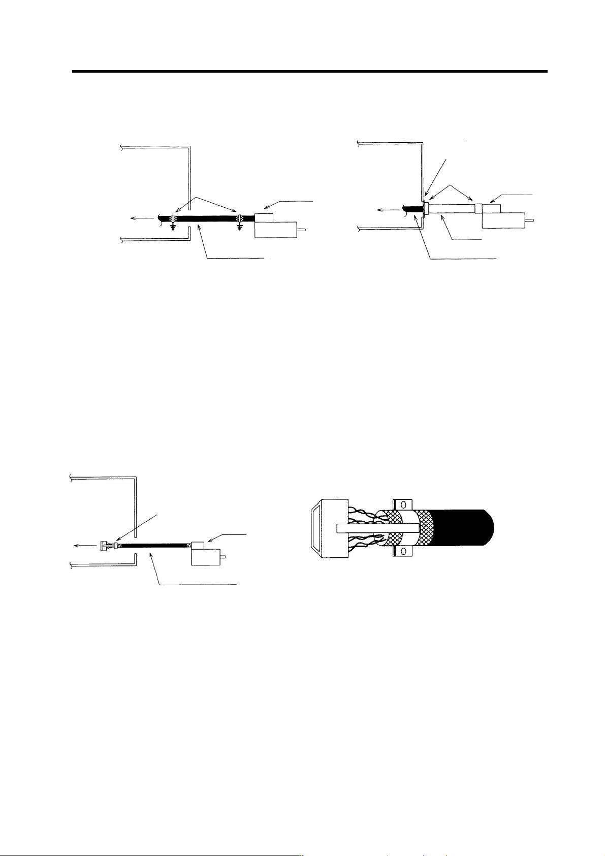
Appendix 3-5-4 Servo motor feedback cable
Use a conventional batch shield pair cable for feed back cable of the servo motor to earth on NC side
(inside the control panel.)
Control panel
To drive unit
Cannon connect or
Batch shield pair c able
Solder
Appendix 3. EMC Installation Guidelines
A3 - 8
Appendix 3-5-5 Spindle motor power cable
Control panel
To drive unit
Earth with
P or U clip
Terminal
box
Shield cable
Spindle moto
r
Control panel
To drive unit
Conduit
connecto
r
Conduit
Cabtyre cable
Terminal
box
Earth with paint mask
Using shield cable Using conduit
(1) Use four wires (3-phase + earthing) for the power cable that are completely shielded and free from
breaks.
(2) Earth the shield in the same manner as the servomotor power cable.
(3) When not using a shield cable for the power cable, use a conventional cabtyre cable. Use a metal
conduit outside the cable.
(4) Earth the power cable on the control panel side at the contact surface of the conduit connector and
control panel side wall in the same manner as the servomotor power cable. (Mask the side wall of
the control panel with paint.)
(5) Earth at the conduit connector section in the same manner as the servomotor power cable.
Appendix 3-5-6 Spindle motor feedback cable
To drive unit
Control panel
Connect with connector case
after shield clamping
Terminal box
Batch pair shield cable
To drive unit
Spindle drive unit side connector (this figure shows when cover is removed)
(1) Use a conventional batch shield cable for feedback cable of the spindle motor.
(Note) Shield of the spindle motor feedback cable is not FG. Do not earth.
Appendix 3. EMC Installation Guidelines
A3 - 9
Appendix 3-6 EMC countermeasure parts
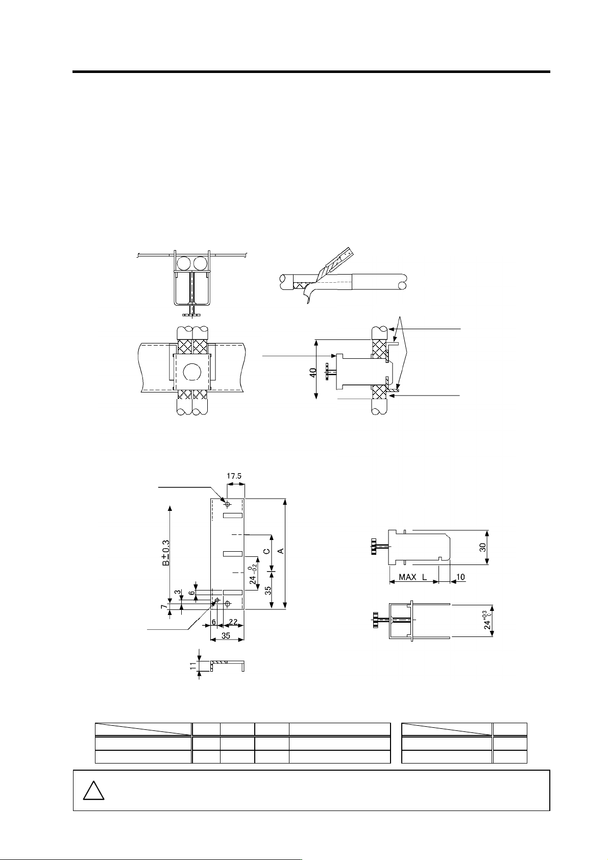
Appendix 3-6-1 Shield clamp fitting
The effect can be enhanced by connecting the cable directly to the earthing plate.
Install an earthing plate near each panel's outlet (within 10cm), and press the cable against the earthing
plate with the clamp fitting.
If the cables are thin, several can be bundled and clamped together.
Securely earth the earthing plate with the frame ground. Install directly on the cabinet or connect with an
earthing wire.
Contact Mitsubishi if the earthing plate and clamp fitting set (AERSBAN-
SET) is required.
View of clamp section
• Outline drawing
Peel the cable sheath at the clamp section.
Cable
Cable
Earthing plate
Earthing plate
Clamp fitting
(Fitting A, B)
Clamp fitting
2-Ø5 hole
Installation hole
[Unit: mm]
Note 1
M4 screw
Shield sheath
(Note 1) Screw hole for wiring to earthing plate in cabinet.
(Note 2) The earthing plate thickness is 1.6mm.
A B C Enclosed fittings
L
AERSBAN-DSET 100 86 30 Clamp fitting A × 2 Clamp fitting A 70
AERSBAN-ESET 70 56 - Clamp fitting B × 1 Clamp fitting B 45
!
Caution
Shield of spindle detector cable is not connected to FG (earth). Do not earth the cable
shield with cable clamp, etc.