MDS-C1-SPA Series INSTRUCTION MANUALib1500152(eng)a.pdf - 第139页
4. Spindle Adjustment 4 - 48 (5) Adjustments during orientation stop [1] Position loop gain adjustment Stop position accuracy can be improve d by incr easing the post-orientation servo rigidity. To increase the post-orie…
4. Spindle Adjustment
4 - 47
[5] Speed clamp value adjustment
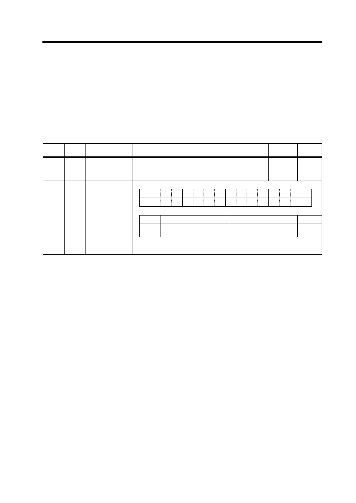
The orientation control mode's position loop control changing speed is determined
automatically, based on the position loop gain, the deceleration rate, and the gear ratio, etc. A
changing speed that is too high can be limited by the orientation mode changing speed limit
value (SP005) setting. A change to the orientation motor speed clamp value 2 (SP115) occurs
at control input 4/bitC. This clamp speed can be clamped in the spindle side speed by setting
the parameter SP037(SFNC5)/bitD=1. If the gear has two or more stages and the cha nge of the
gear rate is large for the gear stage, clamping in the spindle side speed can be stopped more
stably.
No. Abbr. Parameter name Details
Setting
range
Standard
SP005 OSP Orientation mode
speed clamp value
Set the motor speed limit value to be used when the speed loop
is changed to the position loop in orientation mode.
When this parameter is set to "0", SP017 (TSP) becomes the
limit value.
0 to 32767
(r/min)
0
F EDCBA98765 4 3 2 10
dplg ospcl noplg nsno nosg psdir plgo magoenco
bit
Meaning when set to 0 Meaning when set to 1 Standard
D ospcl
Orientation speed clamp
motor speed setting
Orientation speed clamp
spindle speed setting
0
(Note) bitD is valid only for MDS-C1-SPH.
SP037 SFNC5 Spindle function 5
4. Spindle Adjustment
4 - 48
(5) Adjustments during orientation stop
[1] Position loop gain adjustment
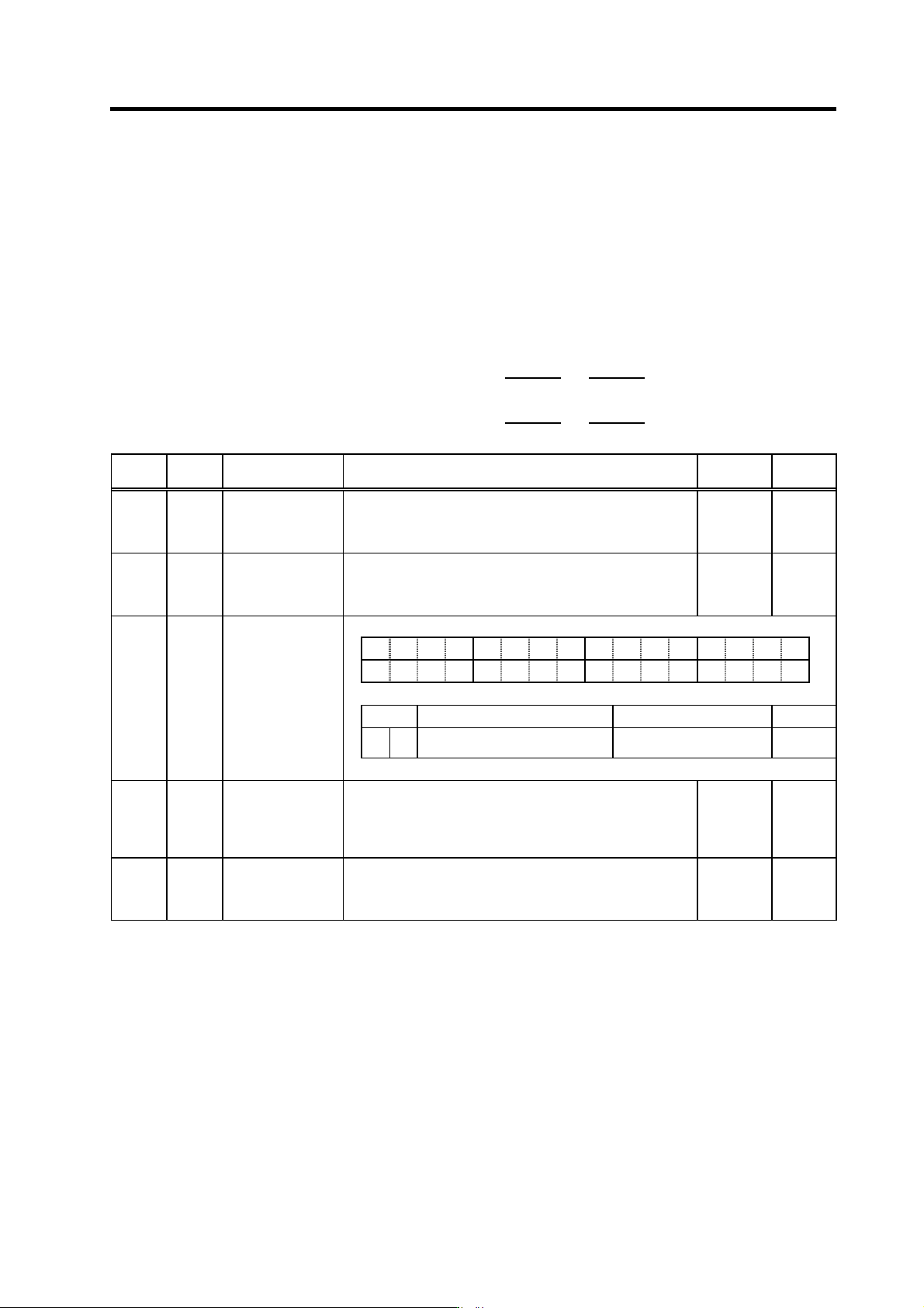
Stop position accuracy can be improved by increasing the post-orientation servo rigidity. To
increase the post-orientation position loop gain, enable a gain change by the SP097/bitC
parameter setting, then set the desired position loop gain magnification. A separate position
loop gain (other than that used during deceleration) can be set for operation that begins from
the orientation completed ON status that follows orientation deceleration control.
The effective position loop gain values for each coil are calculated using the formulas shown
below. If a magnification setting of "0" is set, a "256" setting is adopted.
SP119 SP225
Effective position loop gain (H coil) = SP001 (SP002) ×
256
×
256
SP120 SP226
Effective position loop gain (L coil) = SP001 (SP002) ×
256
×
256
No. Abbr. Parameter name Details
Setting
range
Standard
SP001 PGM* Magnetic sensor,
motor PLG
orientation position
loop gain
The orientation time will be shorter when the value is increased,
and the servo rigidity will increase. On the other hand, the
vibration will increase, and the machine will sway easily.
0 to1000
(0.1rad/s)
100
SP002 PGE* Encoder orientation
position loop gain
<For MDS-C1-SP/SPH/SPM>
The orientation time will be shorter when the value is increased,
and the servo rigidity will increase. On the other hand, the
vibration will increase, and the machine will sway easily.
0 to 1000
(0.1rad/s)
100
F EDCBA98765 4 3 2 10
ostp orze ksft gchg ips2 zdir vg8x mdir fdir oscl pyfx dmin odi2 odi1
bit Meaning when set to 0 Meaning when set to 1 Standard
C gchg
Gain changeover during orientation
invalid
Gain changeover during
orientation valid
0
SP097 SPECO Orientation
specification
SP225 OXKPH* Position loop gain
magnification after
orientation
completed
(H coil)
If gain changeover is valid (SP097: SPEC0/bitC=1) during
orientation, set the position loop gain magnification (H coil)
changed to after orientation completed.
0 to 2560
(1/256-fold)
0
SP226 OXKPL* Position loop gain
magnification after
orientation
completed (L coil)
If gain changeover is valid (SP097: SPEC0/bitC=1) during
orientation, set the position loop gain magnification (L coil)
changed to after orientation complete.
0 to 2560
(1/256-fold)
0
4. Spindle Adjustment
4 - 49
[2] Speed loop gain adjustment
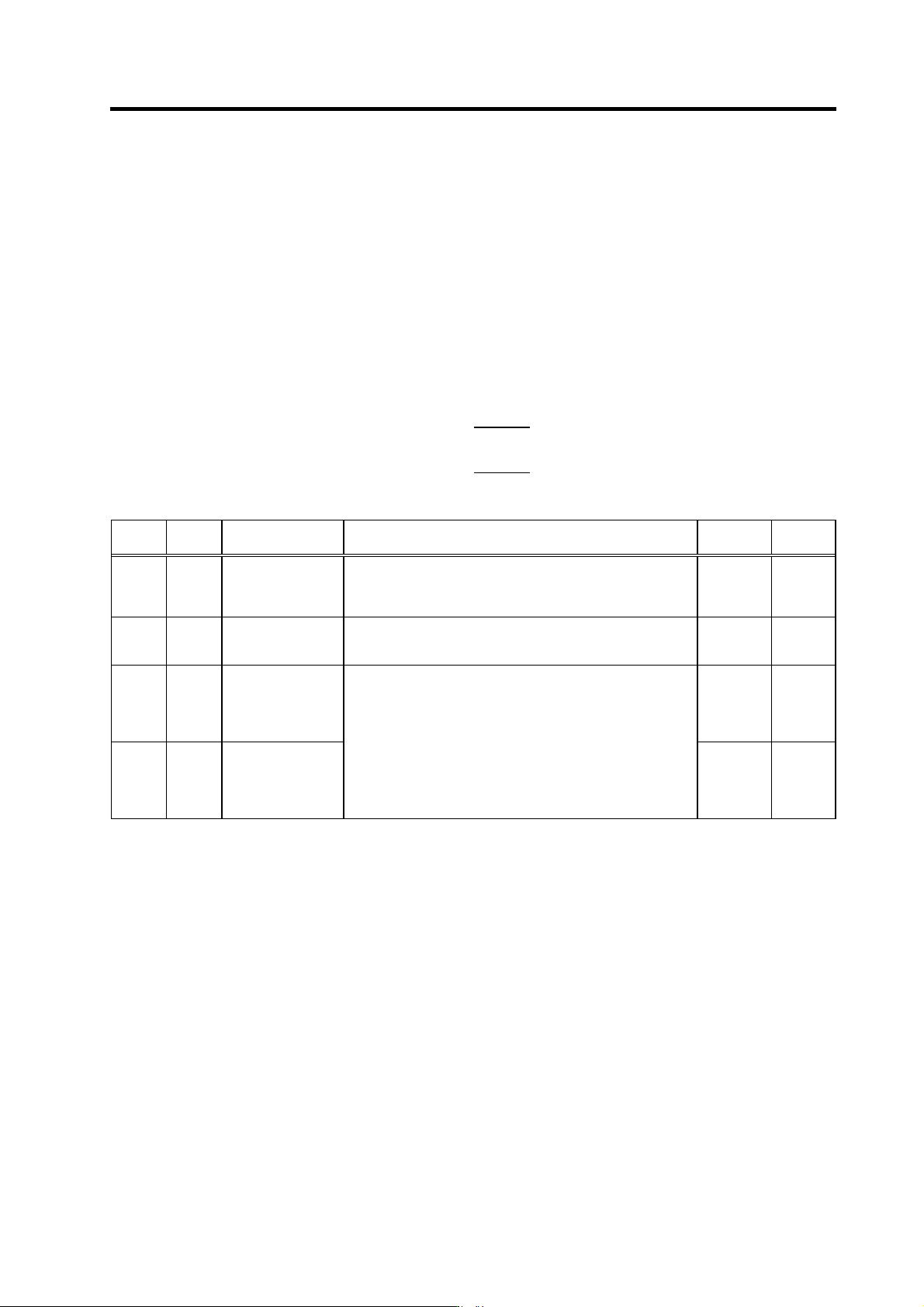
In the same manner as for the position loop gain, a speed loop gain can be set separately fro m
the one used during deceleration for a o peratio n that begins from the orientation completed O N
status, following orientation deceleration control. Although the servo lock rigidity can be
improved by increasing the speed loop g ain during stop, vibration tends to be generated.
To change the post-orientation speed loop gain, enable a gain change by SP097/bitC=1
parameter setting, then set the desired speed loop proportional gain magnification and integral
gain magnification. The proportional and integral gains should be increased at the same rate,
and should be decreased if vibration occurs.
The effective speed loop gains are common to all coils, and are calculated using the formulas
shown below. If a magnification setting of "0" is set, a "256" setting is adopted.
SP227
Effective speed loop proportional gain = SP098 ×
256
SP228
Effective speed loop integral gain = SP099 ×
256
No. Abbr. Parameter name Details
Setting
range
Standard
SP098 VGOP Speed loop gain
proportional term in
orientation control
mode
Set the speed loop proportional gain in orientation control mode.
When the gain is increased, rigidity is improved in the
orientation stop but vibration and sound become larger.
0 to 1000 63
SP099 VGOI Orientation control
mode speed loop
gain integral term
Set the speed loop integral gain in orientation control mode. 0 to 1000 60
SP227 OXVKP* Speed loop
proportional gain
magnification after
orientation
completed
0 to 2560
(1/256-fold)
0
SP228 OXVKI* Speed loop
cumulative gain
magnification after
orientation
completed
If gain changeover is valid (SP097: SPEC0/bitC=1) during
orientation control, set the magnification of each gain changed
to after orientation completed.
0 to 2560
(1/256-fold)
0