MDS-C1-SPA Series INSTRUCTION MANUALib1500152(eng)a.pdf - 第50页
2. Wiring and Connection 2 - 22 (2) Contactor shutoff sequence During the emergency stop signal input (EMG), if the setting of SP193 is "0" or "1" after the spindle motor decelerates to stop, the cont…
2. Wiring and Connection
2 - 21
2-5-3 Main circuit control
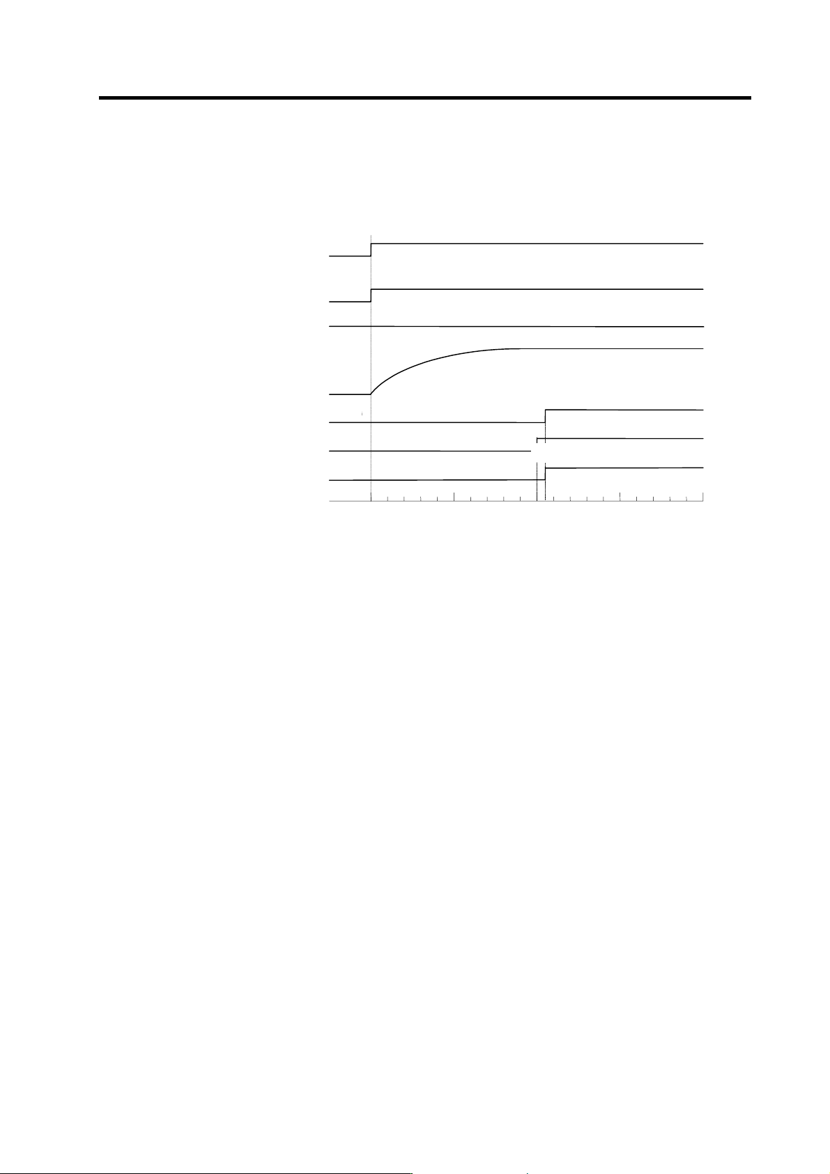
(1) Contactor ON sequence
Main circuit power is turned ON in the sequence shown below when an emergency stop status is
canceled.
OFF
ON
Machine ready complete input
signal (READY)
Emergency stop (EMG)
OFF
ON
Contactor co ntrol ou tp ut (MC1)
ON
OFF
Motor ON (GATE)
ON
OFF
ON
OFF
In read y ON signal (ron)
ON
OFF
Forward run/reverse run signal
(SRN, SRI)
0
500 1000 1500
Time (ms)
Command input enable
Ready completion
・
Contactor ON sequence
PN bus voltage
PN charging completed
2. Wiring and Connection
2 - 22
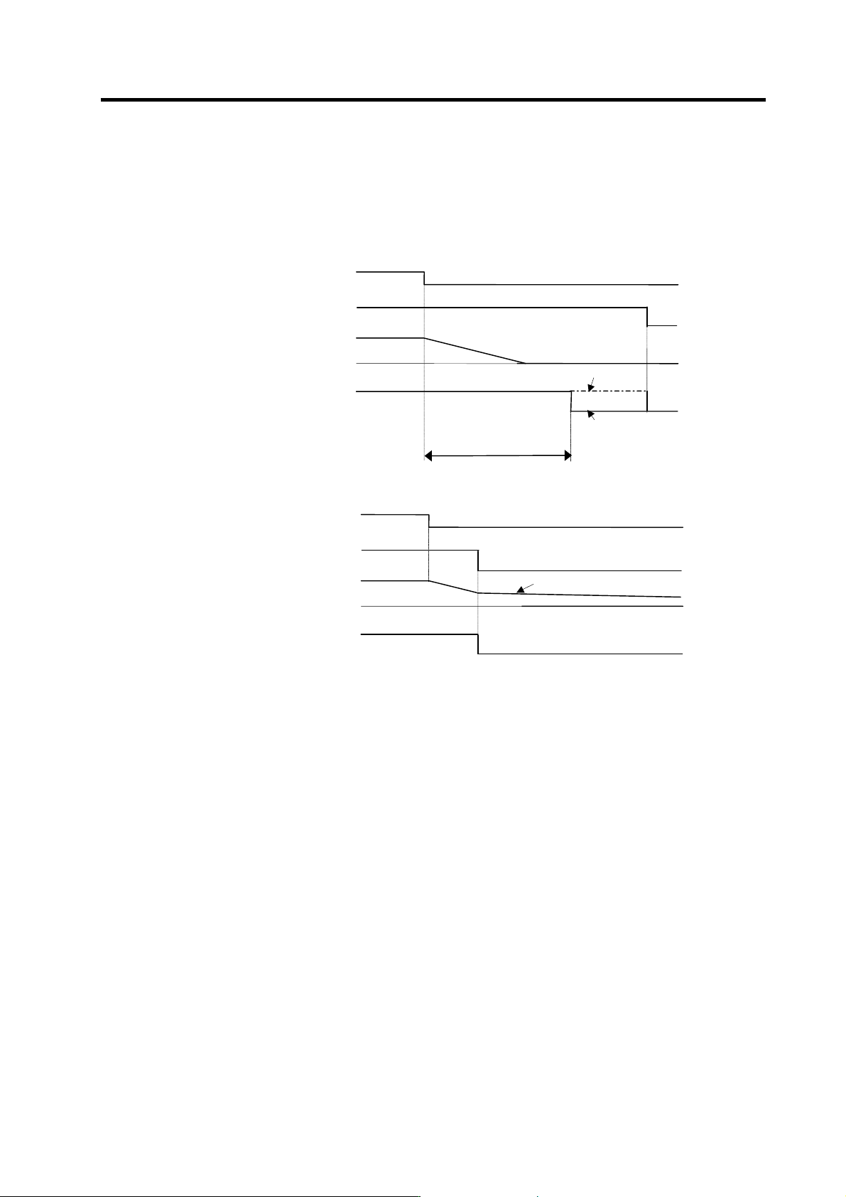
(2) Contactor shutoff sequence
During the emergency stop signal input (EMG), if the setting of SP193 is "0" or "1" after the spindle
motor decelerates to stop, the contactor is turned OFF after a certain amount of time. Even in the
emergency stop, the contactor is turned OFF immediately after the machine ready complete signal
(RDY) is turned OFF.
Machine ready complete input
signal (RDY)
Contactor control output (MC1)
ON
OFF
Contactor OFF sequence (When machine ready complete input signal is input after the setting time of SP055)
SP193: 2,3
OFF
ON
Emergency sto p (EMG)
Spindle motor
(deceleration stop)
0
Speed
OFF
ON
SP193: 0,1
Same as setting value of
SP055
Machine read y complete inpu t
(RDY)
Contactor control output (MC1)
ON
OFF
Contactor OFF sequence (When machine ready complete input signal is input during deceleration stop)
OFF
ON
Emergency stop (EMG)
Spindle motor
0
Speed
OFF
ON
Same as setting value of SP055
Motor coasts to stop.
2. Wiring and Connection
2 - 23
2-6 Peripheral control wiring
2-6-1 Input interface
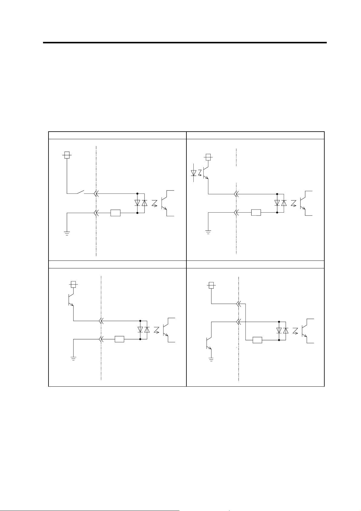
(1) Digital input interface: CN10 to 12
(Special input: 3 points, general-purpose input: 12 points, multi-points orientation command: 12
points, digital speed command: 12 points)
Select from the following.
1) Connecting with contact 2) Connecting with photo coupler
NC(PC) side
+24V
Drive unit side
4.7KΩ
CES
1 to 3
Current capacity
5.1m A or more
NC(PC) side
+24V
Drive unit side
4.7K
Ω
CES
1 to 3
Current
capacity
5.1mA or more
3) Connecting with open emitter 4) Connecting with open collector
NC(PC) side
+24V
Drive unit side
4.7K
Ω
CES
1 to 3
Current
capacity
5.1m A or
more
NC(PC) side
+24V
Drive un it si de
4.7K
Ω
CES 1 to 3
Current
capacity
5.1mA or
more
(Note 1) A +24V(±10%) power supply is required for this unit. The required maximum power supply capacity is 26W. DC stabilized
power supply must be used here.
(Note 2) Common for dedicated/general-purpose input is CES1, common for digital speed command is CES2, and common for
multi-point orientation command is CES3. Each command is electrically separated one another.
Thus, when using CES1, 2 or 3, each of them has to be connected to one of the signals (power supply, etc.).
(Note 3) Filter time constant at the input section is 5 to 15ms.
(Note 4) When running the motor on a trial basis, (when only "machine ready complete", "forward run" and "reverse run" are input
and all the other 24V I/O are not used.), external +24V power supply is exceptionally not necessary; internal +24V power
supply will do. In this case, use CN10-7 pin for +24V, CN10-10 pin for RG (24G).
(Note 5) Power supply unit's CN23 is a similar circuit; however, the resistance is not 4.7kΩ but 2kΩ.