MDS-C1-SPA Series INSTRUCTION MANUALib1500152(eng)a.pdf - 第184页
5. Troubleshooting 5 - 13 Alarm No. 50 Overload 1 The overload detection level reached 100% or mor e. The motor or drive unit is in the overload state. Investigation details Investigation results Remedies The standard va…
5. Troubleshooting
5 - 12
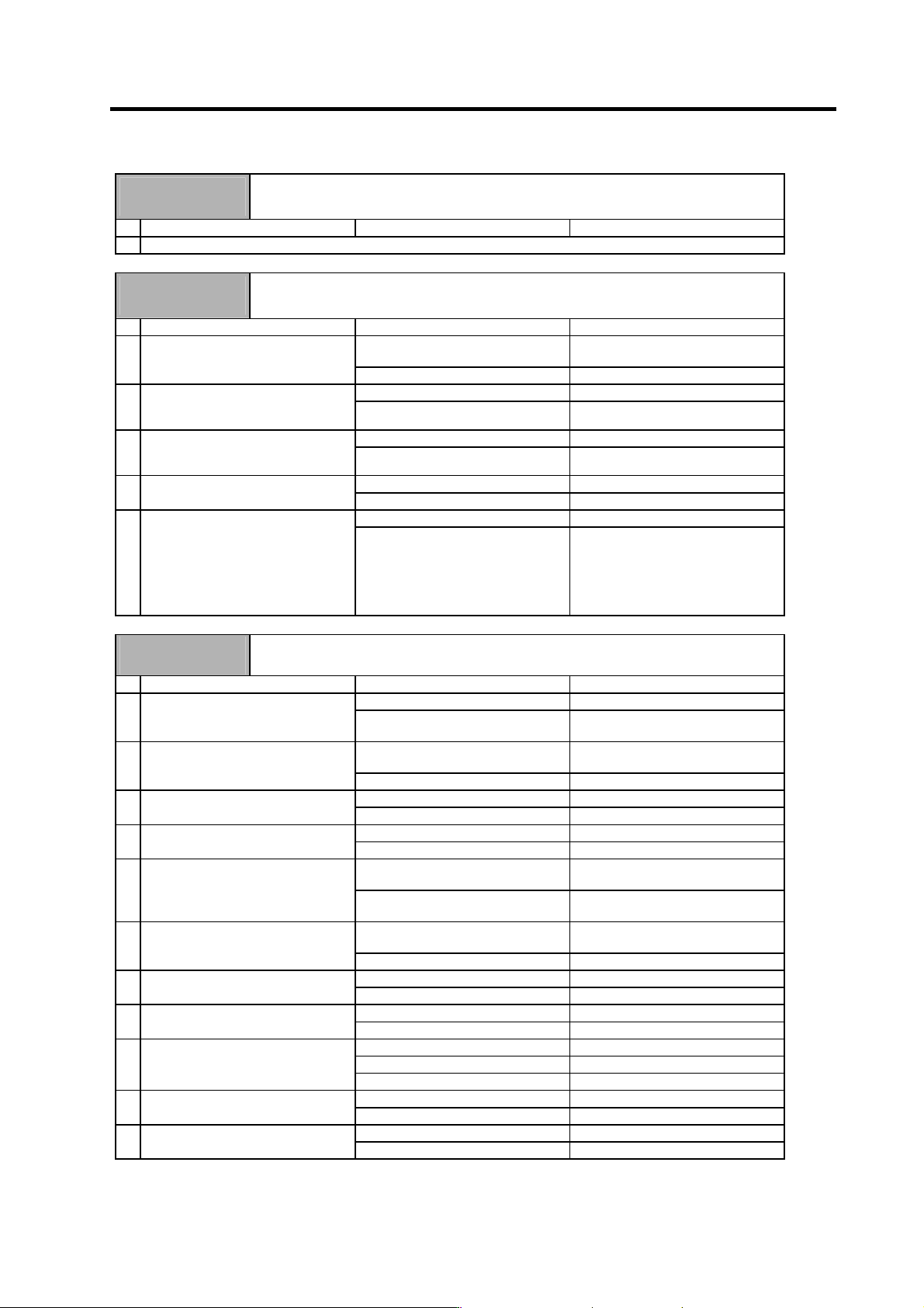
Alarm No.
41
Detector changeover unit, communication error
During 1-drive unit 2-motor control, an error was detected in the communication with the
detector changeover unit.
Investigation details Investigation results Remedies
1 Check the alarm No. "40" items.
Alarm No.
42
Feedback error 1
With the servo, pulse-type position detector feedback signal error was detected. With the
spindle, a PLG feedback signal error was detected.
Investigation details Investigation results Remedies
The connector is disconnected (or
loose).
Correctly install. 1 Check whether the drive unit
connectors (CN6) or detector
connectors are disconnected.
The connector is not disconnected. Investigate item 2.
There is a connection fault. Replace the detector cable. 2 Turn the power OFF, and check the
detector cable connection with a
tester.
The connection is normal. Investigate item 3.
The alarm is on the drive unit side. Replace the drive unit. 3 Connect to another normal drive unit,
and check whether the fault is on the
drive unit side or detector side.
The alarm is on the detector side. Investigate item 4.
There is a problem. Adjust the PLG output waveform. 4 Check the PLG output waveform.
Normal Investigate item 5.
No abnormality is found in particular. Replace the detector. 5 Check if there is any abnormality in
the detector's ambient environment.
(Ex. Ambient temperature, noise,
grounding)
An abnormality was found in the
ambient environment.
Take remedies according to the
causes of the abnormality.
Ex. High temperature:
Check the cooling fan.
Incomplete grounding:
Additionally ground.
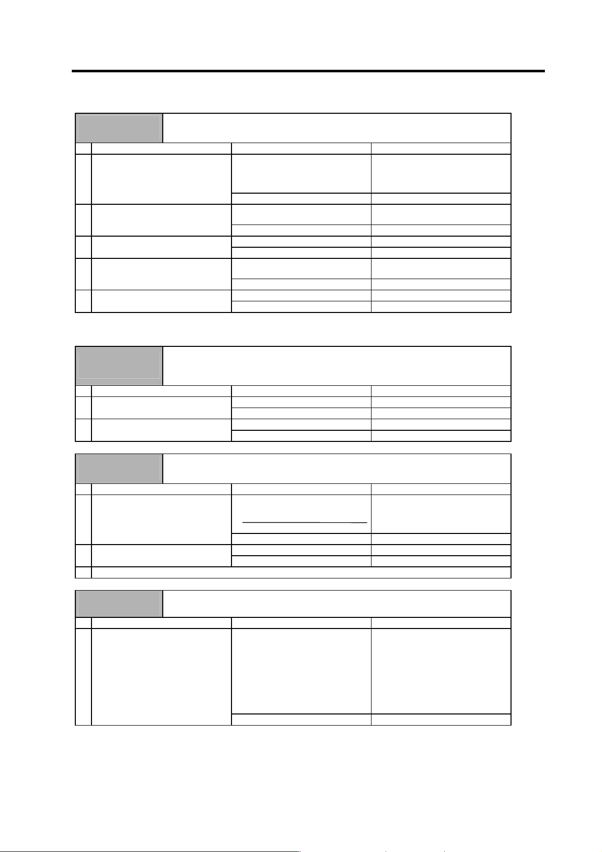
Alarm No.
46
Motor overheat
The temperature protection function in the motor or detector activated.
Investigation details Investigation results Remedies
The alarm occurs before operation. Investigate item 2. 1 Check the repeatability.
The alarm occurs occasionally after
operation is started.
Investigate item 4.
The connector is disconnected (or
loose).
Correctly install. 2 Check whether the drive unit
connectors (CN6) or detector
connectors are disconnected.
The connector is not disconnected. Investigate item 3.
The cable is broken. Replace the cable. 3 Using a tester, check whether the
detector cable is broken.
The cable is not broken. Investigate item 11.
The load is large. Investigate item 7. 4 Check the load meter (spindle).
The load is not large. Investigate item 8.
The constant load torque (friction +
unbalance) is 60% or more.
Select the motor so that the constant
load torque is 60% or less.
5 Is the unbalance torque high?
The constant load torque is less than
60%.
Investigate item 6.
The alarm was forcibly reset. Do not turn the drive unit's power
OFF when an overload alarm occurs.
6 Was the overload alarm (50) forcibly
reset by turning the drive unit power
OFF?
The alarm was not forcibly reset. Investigate item 8.
There was an incorrect setting. Correctly set. 7 Check the parameter settings.
The settings are correct. Investigate item 8.
Hot. Investigate item 9. 8 Measure the motor temperature
when the alarm occurs.
Not hot. Investigate item 11.
The fan motor was stopped. Investigate item 10.
The motor fan wind flow is poor. Clean.
9 When using a motor with fan, check
whether the fan is stopped, or
whether it is clogged with dust, etc.
There is no problem. Investigate item 11.
The cable is broken. Replace the cable. 10 Check the fan wiring.
The cable is not broken. Replace the fan.
Improved. Replace the drive unit. 11 Try replacing the drive unit.
Not improved. Replace the motor.
5. Troubleshooting
5 - 13
Alarm No.
50
Overload 1
The overload detection level reached 100% or more. The motor or drive unit is in the overload
state.
Investigation details Investigation results Remedies
The standard values (below) are not
set.
Servo : SV021 = 60, SV022 = 150
Spindle : SV063 = 60, SP064 = 110
Set the standard values.
1 Check the overload parameters.
SP063, SP064
The standard values are set. Investigate item 2.
The load is large. Servo : Investigate item 3.
Spindle : Investigate item 7.
2 Check the load meter (spindle).
The load is not large. Investigate item 9.
There is a problem. Adjust the PLG output waveform. 3 Check the PLG output waveform.
Normal Investigate item 4.
The motor performance is
insufficient.
Lower the acceleration/deceleration
rate or cutting load.
4 Confirm the motor capacity selection
again.
The motor performance is sufficient. Investigate item 5.
Improved. Replace the drive unit. 5 Try replacing the drive unit.
Not improved. Replace the motor.
(Note) PR resetting is not possible when the overload level is 50% or more. Do not forcibly reset (AR) by turning the unit power
OFF. If AR resetting is used at 50% or higher, the level is set to 80% when the power is turned ON next.
Alarm No.
51
Overload 2
With the servo, a current command exceeding 95% of the unit's maximum current continued
for one second or more. With the spindle, a load exceeding the continuous rating continued
for 30 minutes or more.
Investigation details Investigation results Remedies
The load is large. Lower the load. 1 Check the load meter value.
The load is not large. Investigate item 2.
There is a problem. Adjust the PLG output waveform. 2 Check the PLG output waveform.
Normal Replace the drive unit.
Alarm No.
52
Excessive error 1
The difference between the motor's actual position at servo ON and the theoretical position
exceeded the setting value.
Investigation details Investigation results Remedies
A value larger than the droop amount:
Droop amount =
Spindle rotation speed
×
No. of pulses
60
×
position loop gain
Set appropriate values. 1 Check the excessive error detection
width.
SP102 (Orientation control)
Appropriate values are set. Investigate item 2.
The polarity is reversed. Correctly set the parameters. 2 Check the position detector polarity.
SP097/bit5 (Orientation control)
Normal. Investigate item 3.
3 Check the alarm No. "51" items.
Alarm No.
57
Option error
An input that does not exist in the option settings was selected for the general-purpose input.
Investigation details Investigation results Remedies
The setting value is incorrect.
Drive unit option symbol
None: For 1 to 3, 15 or 17,
setting impossible
R: For 15 or 17, setting impossible
D: For 1 to 3, 15, setting impossible
T: For 1 to 3, 17, setting impossible
RD: For 17, setting impossible
RT: For 17, setting impossible
Change the setting value.
1 Check the spindle parameters SP140
to SP151 settings.
The setting value is correct. Replace the drive unit.
5. Troubleshooting
5 - 14
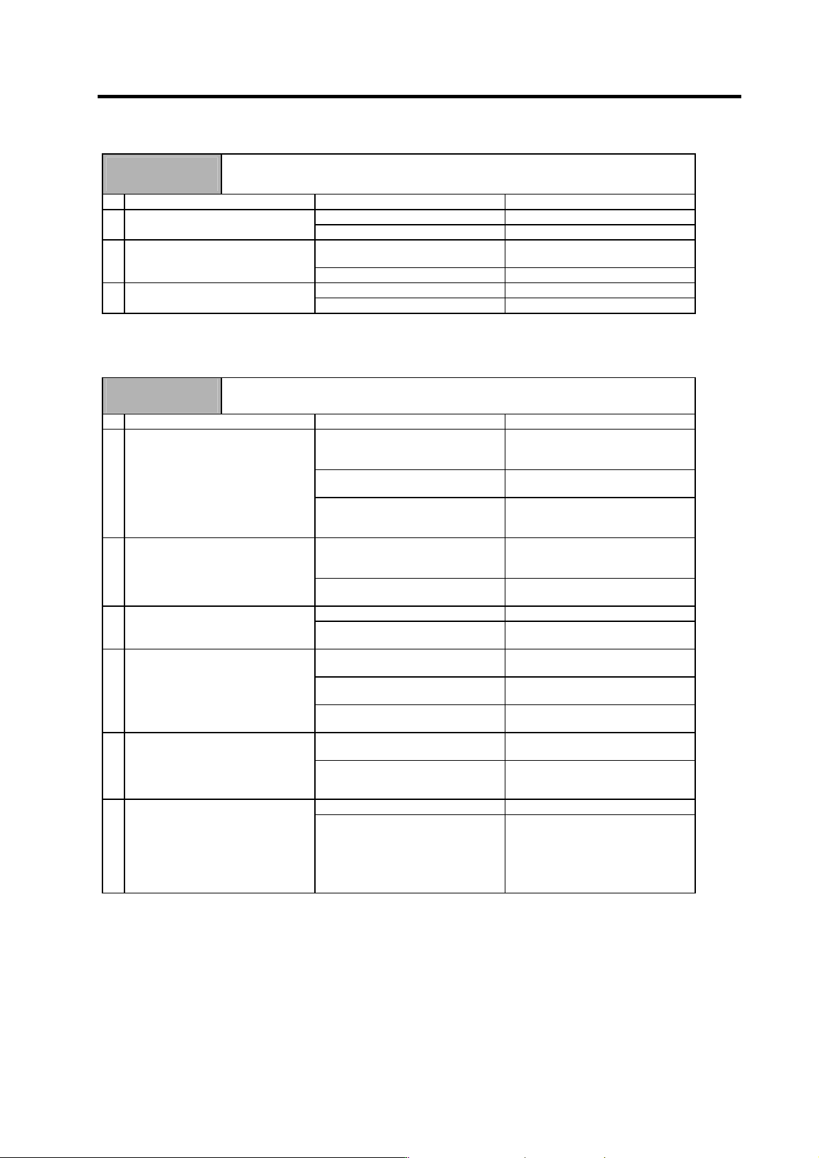
Alarm No.
5C
Orientation feedback error
After orientation was completed, the command and feedback error exceeded the parameter
setting.
Investigation details Investigation results Remedies
The cable is not correctly shielded. Shield the cable. 1 Check the PLG cable shield.
The cable is correctly shielded. Investigate item 2.
The cable is incorrectly connected or
broken.
Replace the cable. 2 Check the PLG cable connection.
Normal Investigate item 3.
There is a problem. Adjust the PLG output waveform. 3 Check the PLG output waveform.
Normal Replace the drive unit
The following alarms of the alarm No. 61 to 77 occur in the power supply unit.
Alarm No.
61
Power module overcurrent
The power module's overcurrent protection function activated.
Investigation details Investigation results Remedies
The alarm occurs immediately after
200VAC is supplied and after READY
is turned ON.
Replace the unit.
The alarm occurs frequently during
READY ON.
Investigate item 3.
1 Check the state of the operation
when the alarm occurs, and check
the repeatability.
The alarm occurs after continuous
operation for a long time.
The unit is hot.
Investigate item 2.
The total load of all motors exceeds
the rated capacity of the power
supply unit.
Lower the motor load and operation
frequency.
2 Check the load state of all motors,
and the starting/stopping frequency.
The total does not exceed the
capacity.
Investigate item 3.
The power capacity is insufficient. Increase the power capacity. 3 Check the power capacity.
The specified power capacity is
secured.
Investigate item 4.
The voltage drops to 170V or less
occasionally.
Increase the power capacity.
The difference of the voltage across
wires is 10V or more.
Improve the power phase balance.
4 Measure the voltage across wires.
• Is the voltage 170V or more even
when the motor is accelerating?
The difference of the voltage across
wires is less than 10V.
Investigate item 5.
The power voltage is distorted. Improve the source of the distortion.
Install an AC reactor.
5 Measure the power voltage with a
synchroscope, and check whether
there is any distortion.
• Are there any other devices
causing the power distortion?
The power voltage waveform is not
abnormal.
Investigate item 6.
No abnormality is found in particular. Replace the unit. 6 Check if there is any abnormality in
the unit's ambient environment.
(Ex. Noise, grounding)
The grounding is incomplete.
An alarm will occur easily if another
device operates.
Take remedies according to the
causes of the abnormality.
Ex. Incomplete grounding:
Additionally ground.
Noise: Noise measures for
other devices.