MDS-C1-SPA Series INSTRUCTION MANUALib1500152(eng)a.pdf - 第97页
4. Spindle Adjustment 4 - 6 Related spindle parameters No. Abbr . Parameter name Details Setting range Standa rd SP129 to SP140 HI01 to HI12 General-purpose input selection1 to general-purpose input selection12 Set the f…
4. Spindle Adjustment
4 - 5
4-2 Spindle control signal
The sequence input/output signals of the spindle drive unit are explained in this section. The status of
each signal is displayed on the spindle monitor of the personal computer when the personal computer
is connected.
4-2-1 Spindle control input (NC to SP)
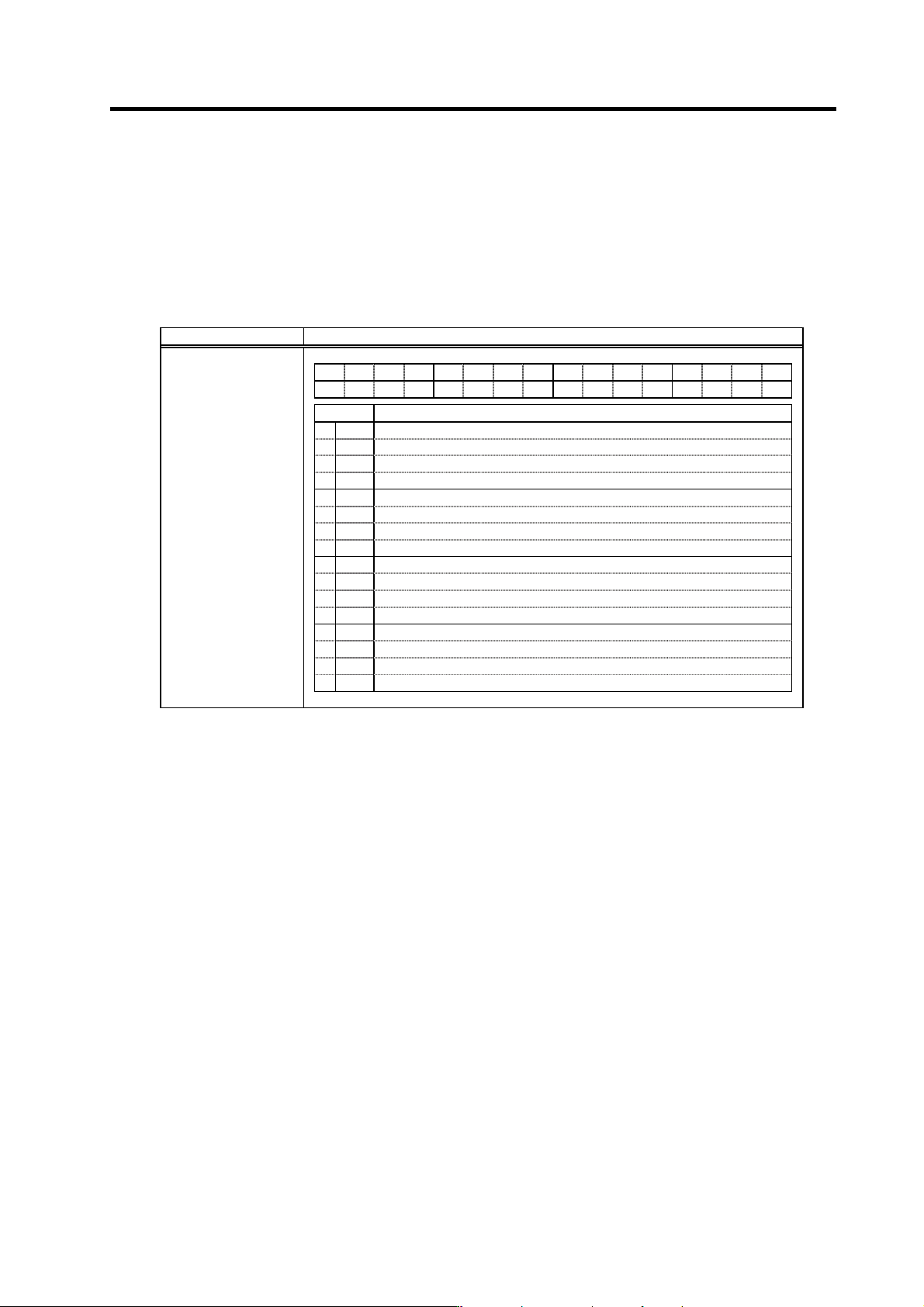
(1) Spindle control input 1
Name Details
F E D C B A 9 8 7 6 5 4 3 2 1 0
TL3 TL2 TL1
ALMR
PRM RDY
bit Details
0
RDY
READY ON command
1
2
3
4
5
6
PRM
Parameter conversion command
7
ALMR
Drive unit alarm reset command
8
TL1
Torque limit 1
9
TL2
Torque limit 2
A
TL3
Torque limit 3
B
C
D
E
F
Spindle control input 1
bit0. READY ON command (RDY)
1) This signal is input when the motor is ready to rotate. This is valid when the circuit between 1 pin
(REDY) and 19 pin (CES1) of CN10 is closed (ON). When this signal is turned ON, the main
circuit of the converter unit will be turned ON.
2) Before this signal is turned ON or within approx. one second from when this signal is turne d ON
till the "in READY ON" signal is turned ON, signals are not accepted even if turning the
forward/reverse run command, orie ntation command ON.
3) If this signal is turned OFF during motor rotation, the current to the motor is shut OFF and the
motor will coast to stop.
4) Turn this signal OFF for safety before the operator touches the spindle directly and
attaches/removes the workpiece or tools. However, be careful not to turn this signal ON/OFF
too frequently (100 times or more/day).
bit6. Parameter conversion command (PRM)
This is started when the spindle parameters are converted on the personal computer screen.
bit7. Drive unit alarm reset command (ALMR)
This turns ON while the alarm reset is input. Spindle alarms are reset.
However, if this signal is turned ON during the motor rotation, the power supplied to the motor is
shut off and the motor will coast to stop.
4. Spindle Adjustment
4 - 6
Related spindle parameters
No. Abbr. Parameter name Details
Setting
range
Standard
SP129
to
SP140
HI01
to
HI12
General-purpose
input selection1
to
general-purpose
input selection12
Set the following value in any one of these parameters when
using the alarm reset.
“9”: Alarm reset
0 to 21 0
bit8. Torque limit 1 (TL1)
bit9. Torque limit 2 (TL2)
bitA. Torque limit 3 (TL3)
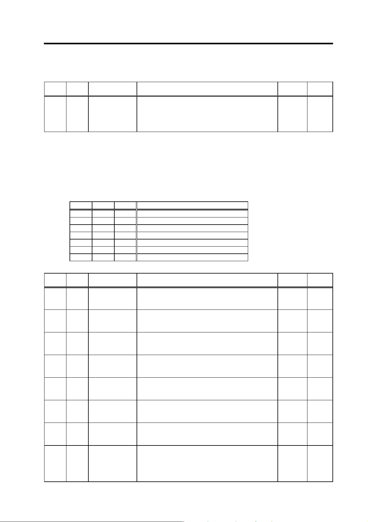
This signal is used to temporarily reduce the spindle motor's output torque such as when clamping
the spindle motor on the machine side. The torque limit is designated in percentage using the
motor's short-time rating as 100%.
Set the SP021, SP049 to SP054 torque limit value with a combination of TL1 to 3.
TL3 TL2 TL1 Torque limit value
0 0 1 SP021
0 1 0 SP049
0 1 1 SP050
1 0 0 SP051
1 0 1 SP052
1 1 0 SP053
1 1 1 SP054
Related spindle parameters
No. Abbr. Parameter name Details
Setting
range
Standard
SP021 TLM1* Torque limit 1 Set the torque limit rate when the torque limit signal 1 is
assigned to the general-purpose input and the input is turned
ON.
0 to 120(%) 10
SP049 TLM2* Torque limit 2 Set the torque li mit rate when the torque limit signal 1, 2 or 1, 2,
3 are assigned to the general-purpose input and only the torque
limit 2 is turned ON.
0 to 120(%) 20
SP050 TLM3* Torque limit 3 Set the torque li mit rate when the torque limit signal 1, 2 or 1, 2,
3 are assigned to the general-purpose input and the torque limit
1, 2 are turned ON.
0 to 120(%) 30
SP051 TLM4* Torque limit 4 Set the torque limit rate when th e torque limit signal 1, 2, 3 are
assigned to the general-purpose input and the torque limit 3 is
turned ON.
0 to 120(%) 40
SP052 TLM5* Torque limit 5 Set the torque limit rate when th e torque limit signal 1, 2, 3 are
assigned to the general-purpose input and the torque limit 1, 3
are turned ON.
0 to 120(%) 50
SP053 TLM6* Torque limit 6 Set the torque limit rate when th e torque limit signal 1, 2, 3 are
assigned to the general-purpose input and the torque limit 2, 3
are turned ON.
0 to 120(%) 60
SP054 TLM7* Torque limit 7 Set the torque limit rate when th e torque limit signal 1, 2, 3 are
assigned to the general-purpose input and the torque limit 1, 2,
3 are all turned ON.
0 to 120(%) 70
SP129
to
SP140
HI01
to
HI12
General-purpose
input selection1
to
general-purpose
input selection12
Set the following value in any one of these parameters when
using the torque limit.
“4”: Torque limit signal1 (TL1)
“5”: Torque limit signal2 (TL2)
“6”: Torque limit signal3 (TL3)
0 to 21 0
4. Spindle Adjustment
4 - 7
(2) Spindle control input 2
Not used.
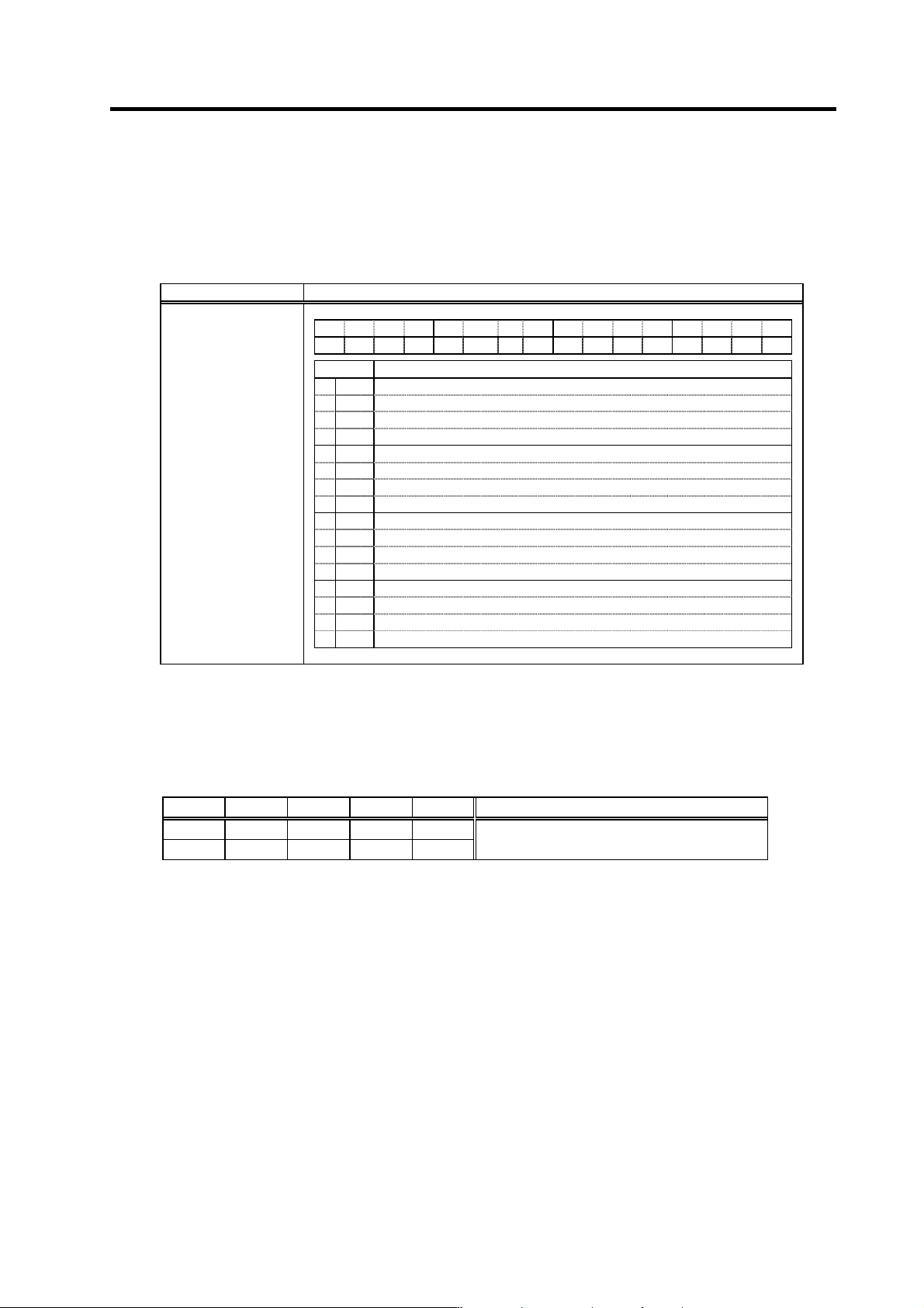
(3) Spindle control input 3
Name Details
F E D C B A 9 8 7 6 5 4 3 2 1 0
MsI
LCS ORC WRI WRN SRI SRN GR2 GR1 SC5 SC4 SC3 SC2 SC1
bit Details
0
SC1
Spindle control mode selection command 1
1
SC2
Spindle control mode selection command 2
2
SC3
Spindle control mode selection command 3
3
SC4
Spindle control mode selection command 4
4
SC5
Spindle control mode selection command 5
5
GR1
Gear selection command 1
6
GR2
Gear selection command 2
7
8
SRN
Forward run start command
9
SRI
Reverse run start command
A
WRN
Indexing forward run command
B
WRI
Indexing reverse run command
C
ORC
Orientation start command
D
LCS
L coil selection command (When using coil changeover motor)
E MsI Sub-motor selection command (for 1-drive unit 2-motor changeover)
F
Spindle control input 3
bit0. Spindle control mode selection command 1 (SC1)
bit1. Spindle control mode selection command 2 (SC2)
bit2. Spindle control mode selection command 3 (SC3)
bit3. Spindle control mode selection command 4 (SC4)
bit4. Spindle control mode selection command 5 (SC5)
SC5 SC4 SC3 SC2 SC1 Control mode
0 0 0 * *
0 0 1 * *
Speed control
(Note) The asterisk indicates 1 or 0.
Since this input is automatically created inside, particular attention is not required.