MDS-C1-SPA Series INSTRUCTION MANUALib1500152(eng)a.pdf - 第25页
1. Installation 1 - 10 (3) Magnet and sensor installation directions • Install so that the magnet's reference hol e and sensor's reference notch are aligned. (Standard/high-speed standards) • Install so that th…
1. Installation
1 - 9
1-3 Installing the spindle detector
1-3-1 Magnetic sensor
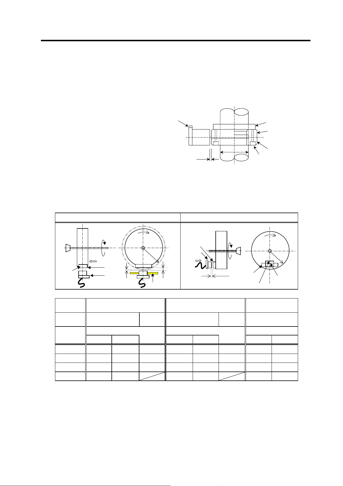
(1) Installing the magnetic sensor
• Tolerance to shaft dimension should
be "h6" on the part for installing a
magnet.
• 2-øG hole can be used for positioning
of spindle and magnet.
• Magnet shall be installed as shown to
the right.
• Misalignment between sensor head
and magnetic center line shall be
within ±2mm.
• There is an NS indication on the side of
the cover. Install so that the reference
notch on the sensor head comes to the
case side.
Gap
Reference notch
Reference drawing for magnet installat i on
G hole
h6
Spindle
Case
Cover
Spindle damping scre
w
(2) Gap between magnet and sensor
Circumference installation
Horizontal installation
Magnet
model
BKO-C1810H03 BKO-C1730H06 BKO-C1730H09
Installation
direction
Circumference
installation
Horizontal
installation
Circumference
installation
Horizontal
installation
Circumference
installation
Gap mm Gap mm Gap mm
R (Radius)
mm
Max. value Min. value Max. value Min. value Max. value Min. value
40 11.5±0.5 2.7±0.5 6.0±0.5 10.0±0.5 1.22±0.5 5.0±0.5 6.25±0.5 3.30±0.5
50 9.5±0.5 2.8±0.5 6.0±0.5 8.0±0.5 1.31±0.5 5.0±0.5 6.00±0.5 3.70±0.5
60 8.5±0.5 3.0±0.5 6.0±0.5 7.0±0.5 1.50±0.5 5.0±0.5 5.75±0.5 3.85±0.5
70 8.0±0.5 3.4±0.5 7.0±0.5 2.38±0.5 5.50±0.5 3.87±0.5
Reference
hole
Reference
notch
Magnet
Min. gap
Max. gap
Mounting plate
R
Direction of
rotation
NS
Spindle
Face A
Face A
Magnet
Gap
R
N
S
Spindle
Face B
Face B
Reference
hole
Reference
hole
Reference
notch
Direction of
rotation
Reference
notch
1. Installation
1 - 10
(3) Magnet and sensor installation directions
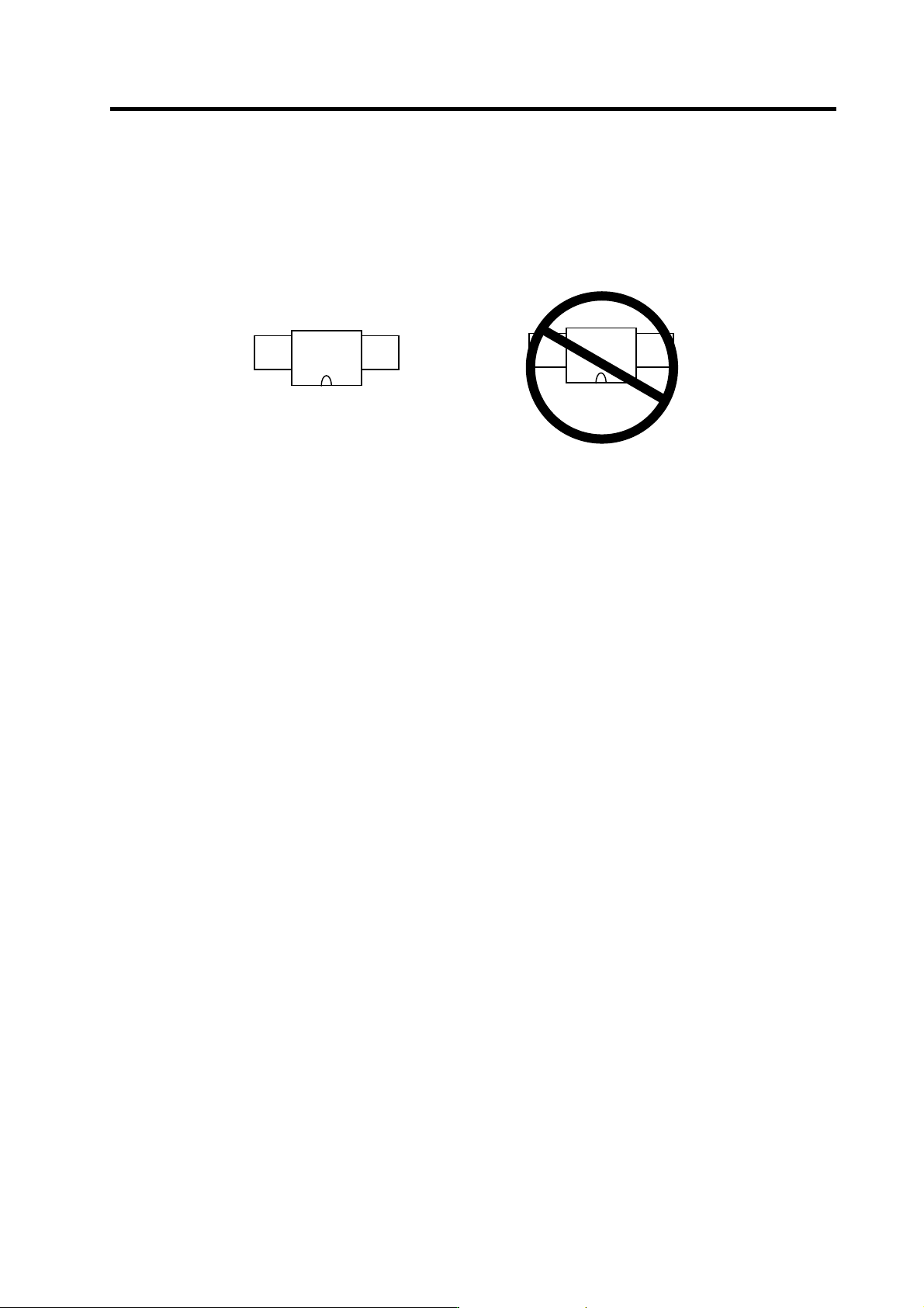
• Install so that the magnet's reference hole and sensor's reference notch are aligned.
(Standard/high-speed standards)
• Install so that the magnet's N pole comes to the left side when the sensor's reference notch is
faced downward. (High-speed compact/high-speed ring)
(4) Cautions
[1] Do not apply impacts on the magnet. Do not install strong magnets near the magnet.
[2] Sufficiently clean the surrounding area so that iron chips and cutting chips do not adhere to the
magnet. Demagnetize the round disk before installing.
[3] Securely install the magnet onto the spindle with an M4 screw. Take measures to prevent
screw loosening as required.
[4] Balance the entire spindle rotation with the magnet installed.
[5] Install a magnet that matches the spindle's rotation speed.
[6] When installing the magnet onto a rotating body's plane, set the speed to 6,000r/min or less.
[7] Install so that the center line at the end of the head matches the center of the magnet.
[8] The BKO-C1730 is not an oil-proof product. Make sure that oil does not come in contact with
BNO-C1730 or BKO-C1810.
[9] When connecting to the spindle drive unit, wire so that the effect of noise is suppressed.
N S
|
Reference notch
Sensor
Magnet
S N
|
Reference notch
Sensor
Magnet
1. Installation
1 - 11
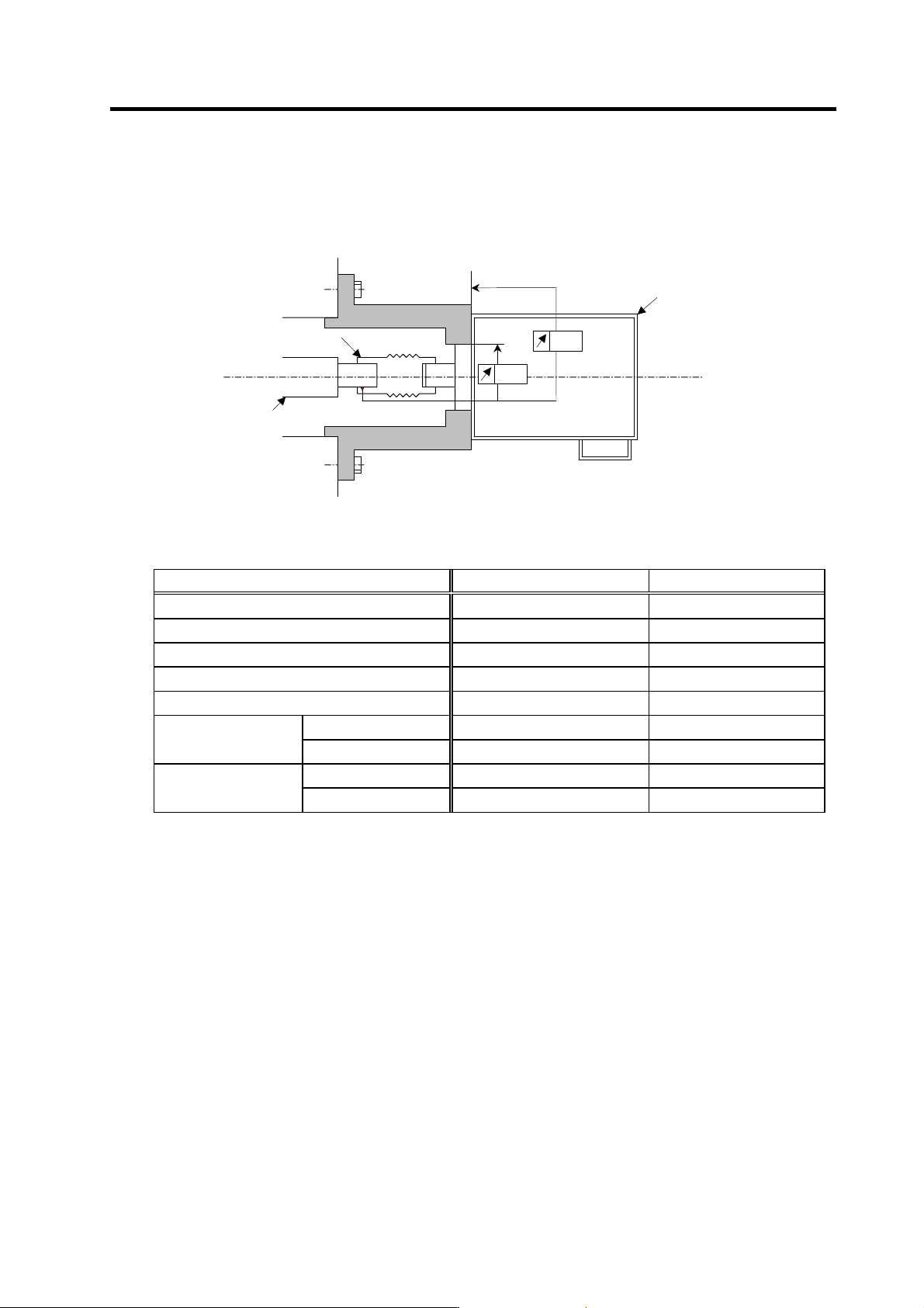
1-3-2 Spindle side detector
When coupling the spindle side detector with spindle, a flexible coupling should be used to couple the
spindle side detector with the spindle.
Detector
0.02
0.02
Opposite detector shaft
side
Flexible coupling
Detector and coupling installation accuracy
Recommended coupling
Recommendation 1 Recommendation 2
Manufacturer Tokushu Seiko Eagle
Model Model M1 FCS38A
Resonance frequency 1374Hz 3515Hz
Position detection error 0.8×10⁻³° 1.2×10⁻³°
Tolerable speed 20000r/min 10000r/min
Core deviation 0.7mm 0.16mm
Mis-alignment
Angle displacement
1.5° 1.5°
Max. length 74.5mm 33mm
Outline dimensions
Max. diameter
ø57mm ø38mm
Refer to the coupling catalog, etc., for details on the coupling.