MDS-C1-SPA Series INSTRUCTION MANUALib1500152(eng)a.pdf - 第61页
3 - 1 3. Set up 3-1 Initia l setup ............................................................................................................. ........................... 3-2 3-1-1 Setting the rotary switch ...........…
2. Wiring and Connection
2 - 32
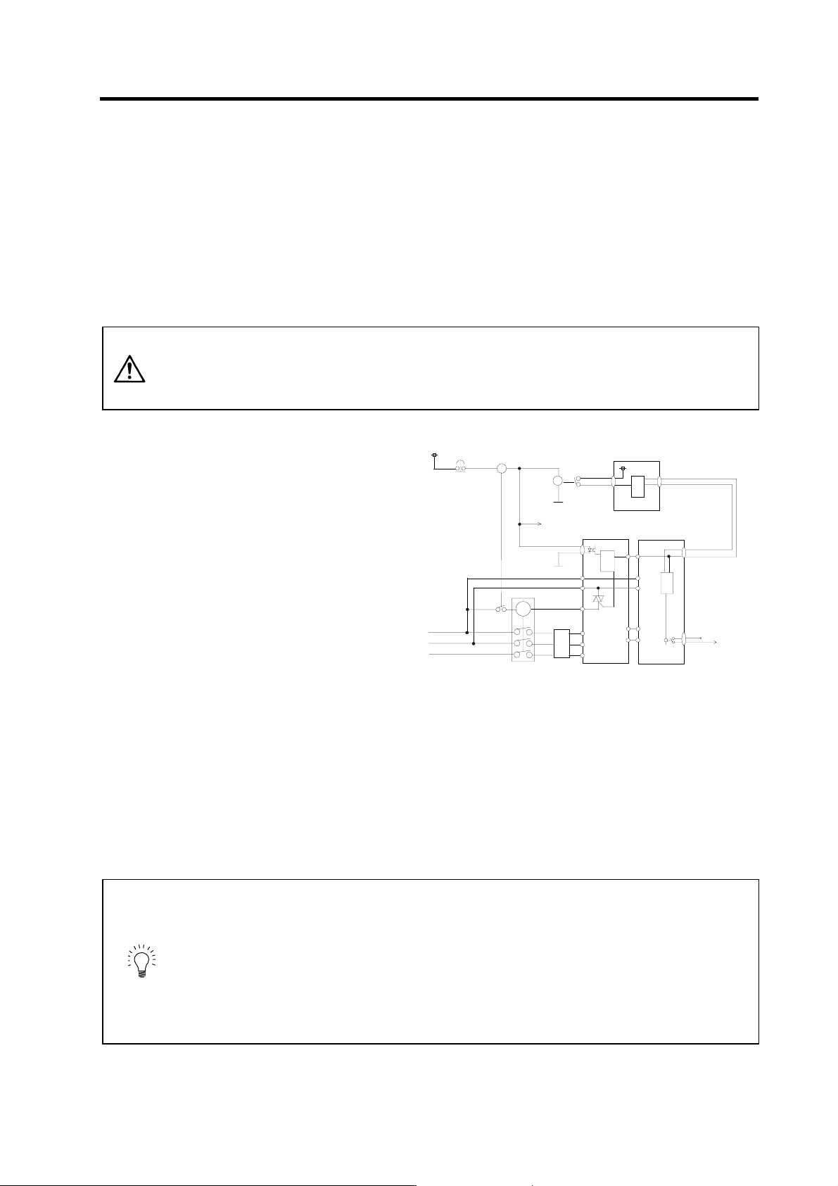
(3) Example of emergency stop circuit
[1] Outline of function
The power supply unit's external emergency stop can be validated by wiring to the CN23
connector, and setting the parameters and rotary switch. If the emergency stop cannot be
processed and the external contractor cannot be shut off (due to a fault) by the spindle drive unit,
the external contactor can be shut off by the power supply unit instead of the spindle drive unit.
At this time, the spindle motor will coast to stop.
EN60204-1 Category 1 can be basically complied with by inputting the external emergency stop
and installing contactor.
CAUTION
1. The power supply unit external emergency stop function is a function that
assists the NC emergency stop.
2. It will take 30 seconds for the external contactor to function after the
emergency stop is input to CN23. (This time is fixed.)
[2] Outline of function
The emergency stop is a signal used
to stop the machine in an emergency.
This is connected to the NC unit. Wire
to the power supply unit when
necessary.
The servo/spindle unit will be
decelerated and controlled by the
software according to the emergency
stop command issued from the NC
unit. (The deceleration control
depends on a parameter setting.)
The diagram on the right shows an
example of the emergency stop circuit
(EN60204-1 Category 0 stop) in which
an off delay timer (TM1) is installed as
a power shutoff method independent from the NC emergency stop input. The required safety
category may be high depending on the machine and the Safety Standards may not be met. Thus,
always pay special attention when selecting the parts and designing the circuit.
[3] Setting the off delay timer (TM1) tim e
Set the TM1 operation time so that it functions after it has been confirmed that all axes have
stopped. If the set time is too short, the spindle motor will coast to a stop.
tm ≥ All axes stop time
Provide a mechanism that shuts off the power even if the NC system fails.
POINT
Stop Categories in EN60204-1
Category 0: The power is instantly shut off using machine parts.
Category 1: The drive section is stopped with the control (hardware/software
or communication network), and then the power is instantly shut
off using machine parts.
(Caution) Refer to the Standards for details.
Refer to Section 9.2.5.4.2 in EN60204-1: Safety of Machinery
Electrical Equipment of Machines – Part 1.
GND
R
R
GND
External
Emergency
Switch
TM1
RA1
MBR*
EMG
CUP
&
ASIC
SV1/2
CN23
Hardware Emergency
Software Emergency
NC Unit
Power Supply
Unit
Servo/Spindle
Drive Unit
CN1A/B
CUP
&
ASIC
CUP
&
ASIC
MC-OF F*
MC1
L1
L2
L3
L21
L11
CN4
CN4
CN20
MBR*
Motor
Brake
AC Reactor
External
Contactor
MC
L21
L11
P
N

3 - 1
3. Setup
3-1 Initial setup........................................................................................................................................ 3-2
3-1-1 Setting the rotary switch ............................................................................................................ 3-2
3-1-2 Transition of LED display after power is turned ON .................................................................. 3-3
3-2 Setting the initial parameters for the spindle drive unit..................................................................... 3-4
3-2-1 Parameter setting method ......................................................................................................... 3-4
3-2-2 List of spindle parameters.......................................................................................................... 3-6
3-3 Initial adjustment of the spindle PLG .............................................................................................. 3-26
3-3-1 Adjusting the PLG installation.................................................................................................. 3-26
3. Setup
3 - 2
3-1 Initial setup
3-1-1 Setting the rotary switch
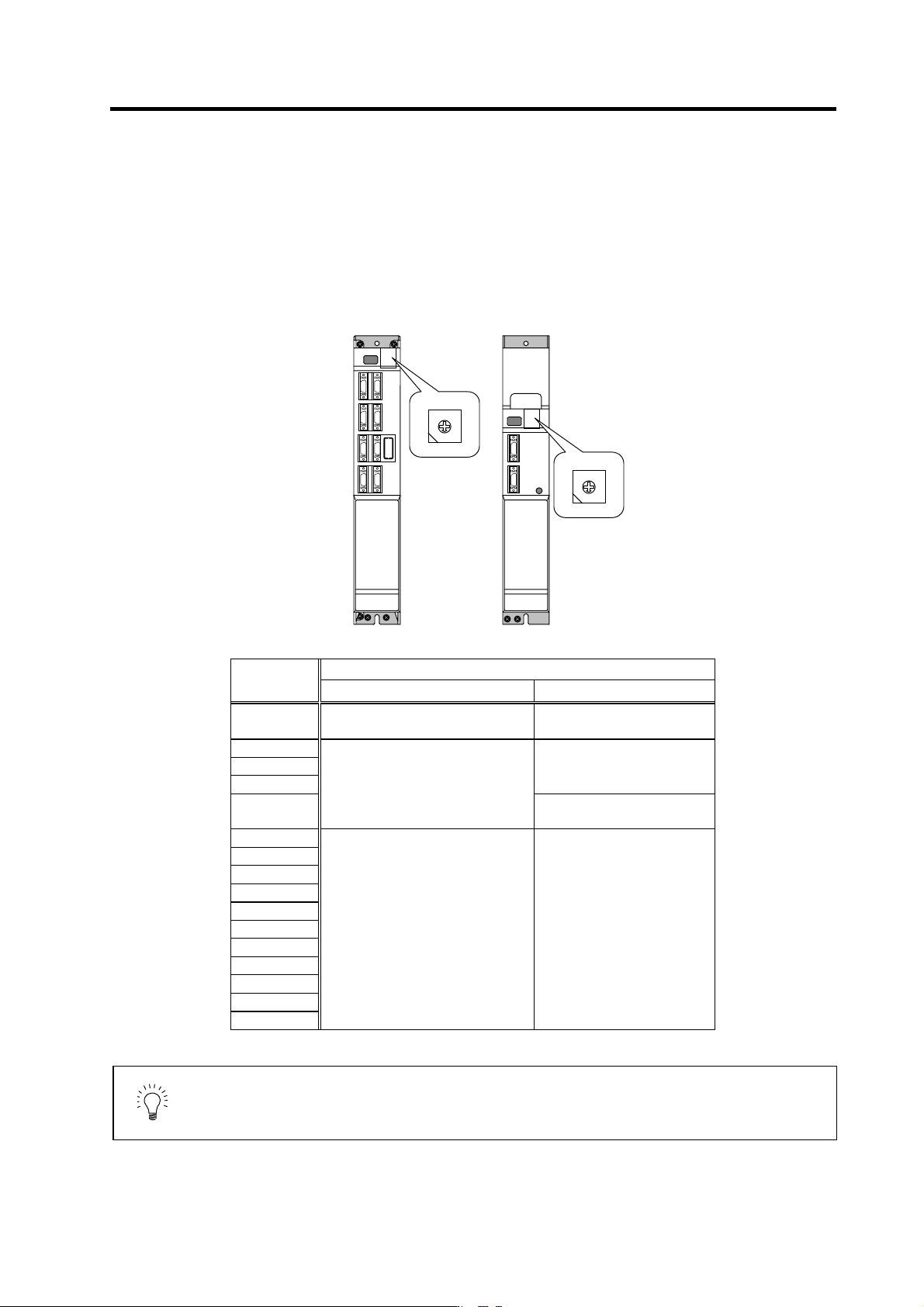
Before turning on the power, the settings of the spindle drive unit and power supply unit's rotary
switches must be confirmed and changed.
Details
Setting the
rotary switch
Setting the MDS-C1- SPA Setting the MDS-C1-CV
0
Apply this setting when the power is
turned ON.
External emergency stop
invalid
1
2 Setting prohibited
3
4
Set when the parameter setting is
confirmed and changed.
External emergency stop valid
(Used CN23)
5
6
7
8
9
A Setting prohibited
B
C
D
E
F
Setting prohibited
POINT
Even if multiple spindle drive units are used for the same machine, set "0" for
the settings of all spindle drive units' rotary switches before the power is turned
ON.
Spindle drive unit
(MDS-C1-SPA)
Power supply unit
(MDS-C1-CV)
0
1 F
2 E
4 C
3 D
5 B
6 A
7 9
8
0
1 F
2 E
4 C
3 D
5 B
6 A
7 9
8