MDS-C1-SPA Series INSTRUCTION MANUALib1500152(eng)a.pdf - 第85页
3. Setup 3 - 25 No. Abbr. Parameter name Details Setting rang e (Unit) Standard setting SP253 DA1NO* D/A output channel 1 data number Set the output data number for channel 1 of the D/ A output function. When set to &quo…
3. Setup
3 - 24
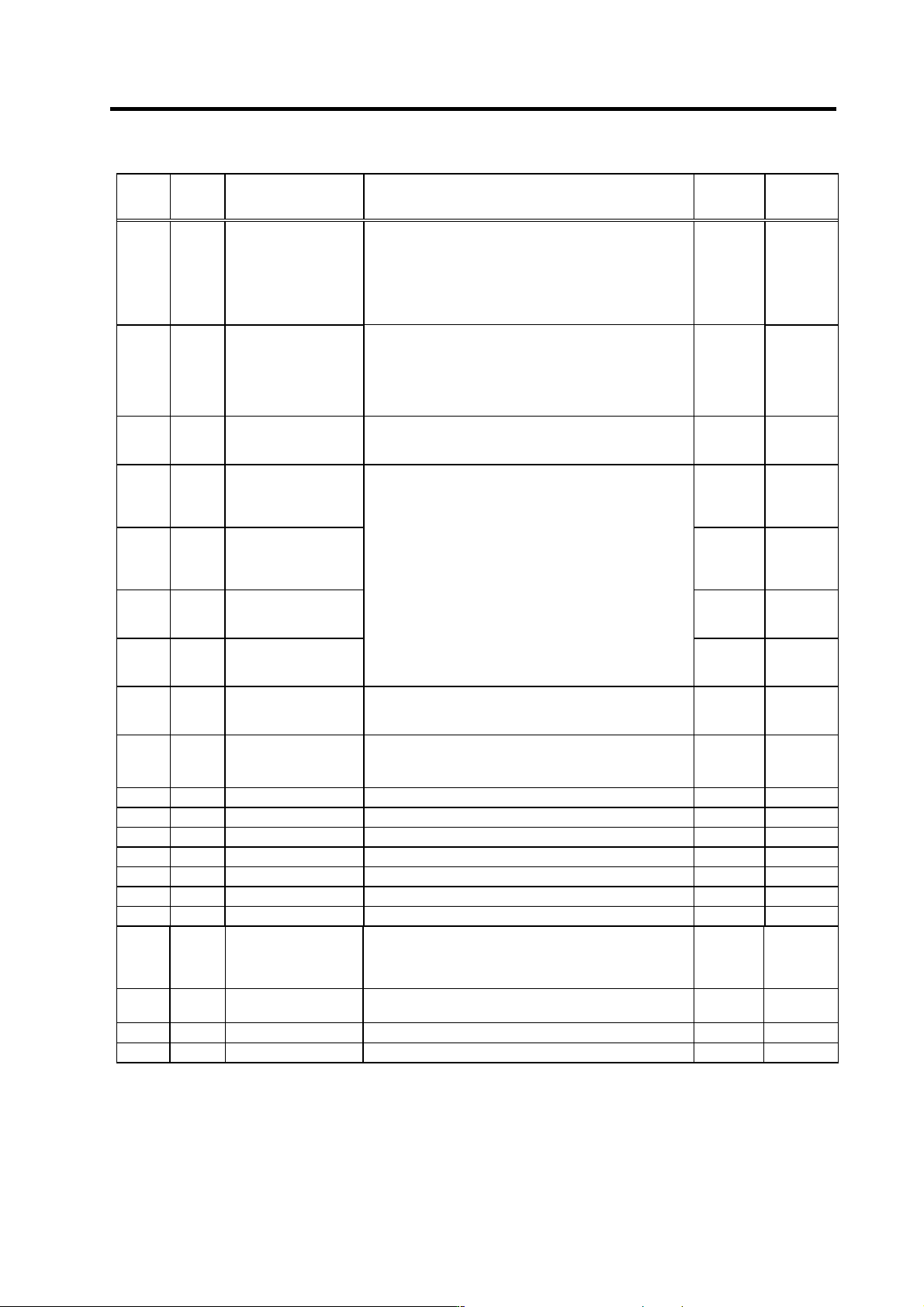
No. Abbr. Parameter name Details
Setting
range
(Unit)
Standard
setting
SP194 SE2R*
Speed excessive
deflection 2 detection
range
Set the speed detection width when the speed excessive
deflection 2 alarm is output. The setting is as follows.
Detection width =
Speed command × current setting value/100 (r/min)
When the result of the expression above is smaller than
45r/min, the detection width is clamped at 45r/min. When
"0" is set, detection will not be carried out.
0 to 100
(%)
0
SP195 SE2T*
Speed excessive
deflection 2 detection
time
Set the duration required to detect the alarms indicated
above.
The speed excessive deflection 2 alarm is output when a
speed deflection larger than the speed detection width is
continued for more than the duration set here.
When "0" is set, detection will be carried out instantly.
0 to 3000
(ms)
0
SP196
to
SP224
Not used. Set "0". 0 0
SP225 OXKPH*
Position loop gain
magnification after
orientation completed
(H coil)
0 to 2560
(1/256-fold)
0
SP226 OXKPL*
Position loop gain
magnification after
orientation completed
(L coil)
0 to 2560
(1/256-fold)
0
SP227 OXVKP*
Speed loop proportional
gain magnification after
orientation completed
0 to 2560
(1/256-fold)
0
SP228 OXVKI*
Speed loop cumulative
gain magnification after
orientation completed
If gain changeover is valid (SP097: SPEC0/bitC=1) during
orientation control, set the magnification of each gain
changed to after orientation completed.
0 to 2560
(1/256-fold)
0
SP229 OXSFT*
Orientation virtual target
shift amount
Set the amount to shift the target position when orientation
virtual target position is valid (SP097: SPEC0/bitD=1).
0 to 2048
(360
deg/4096)
0
SP230
to
SP241
Not used. Set "0". 0 0
SP242 Vavx* Fixed control constant Set by Mitsubishi. Set "0" unless designated in particular. 0 to 32767 0
SP243 UTTM* Fixed control constant Set by Mitsubishi. Set "0" unless designated in particular. 0 to 5000 0
SP244 OPLP* Fixed control constant Set by Mitsubishi. Set "0" unless designated in particular. 0 to 4096 0
SP245 PGHS* Fixed control constant Set by Mitsubishi. Set "0" unless designated in particular. 0 to 1 0
SP246 Not used. Set "0". 0 0
SP247 Not used. Set "0". 0 0
SP248 FNC Fixed control constant Set by Mitsubishi. Set "0" unless designated in particular. 0 to 7 0
SP249 SMO* Speed meter speed
Set the motor rotation speed when the speed meter 10V is
output.
When set to "0", this parameter becomes the same as
SP017 (TSP).
0 to 32767
(r/min)
0
SP250 LMO* Load meter voltage
Set the voltage when the load meter 120% is output. When
set to "0", this becomes 10V.
0 to 10 (V) 0
SP251 Not used. Set "0". 0 0
SP252 Not used. Set "0". 0 0
Parameters having an abbreviation with "*" (SE2R*, etc.) are validated right after the settings are changed by the personal
computer, without turning the spindle drive unit's power ON and OFF.
3. Setup
3 - 25
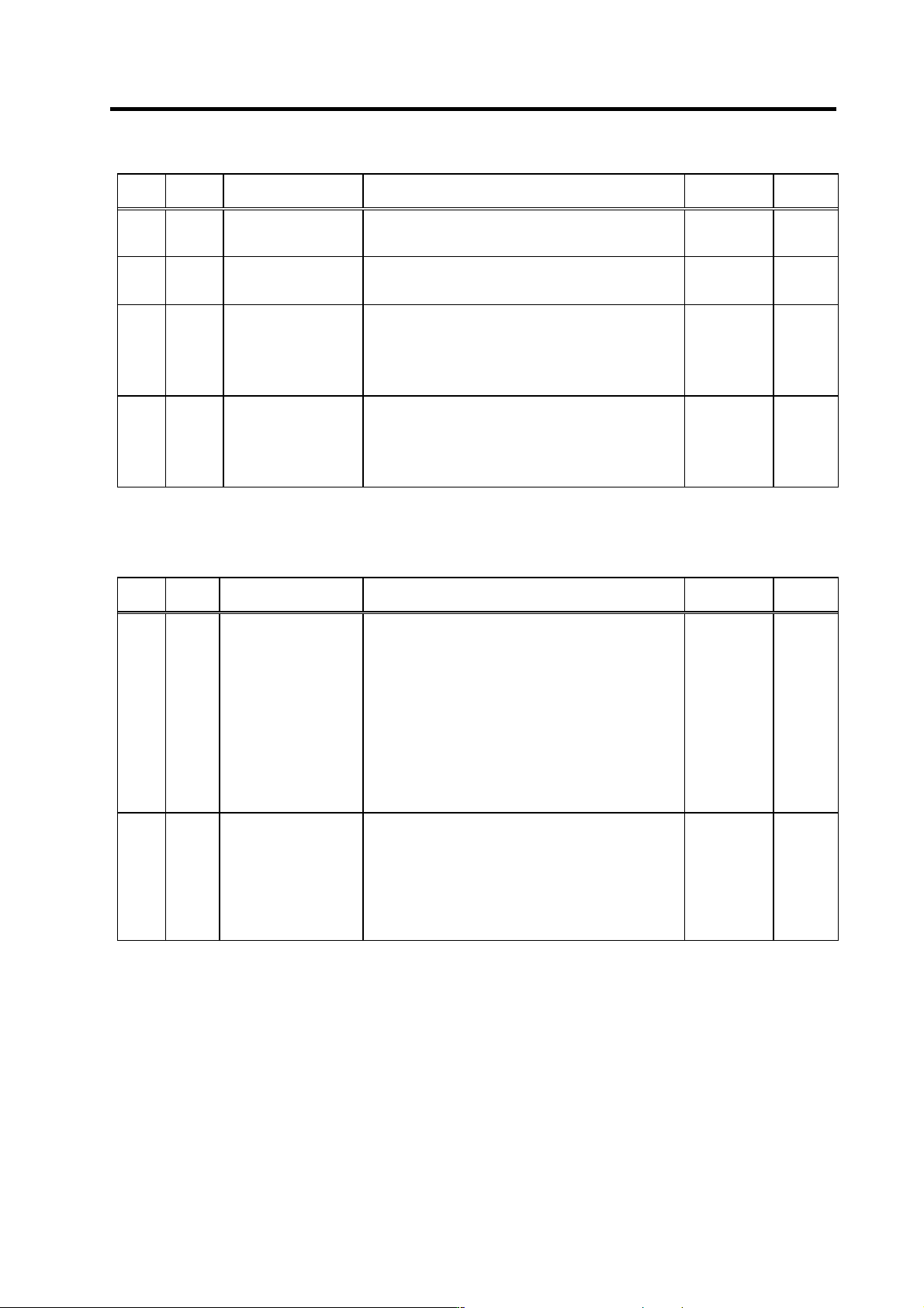
No. Abbr. Parameter name Details
Setting range
(Unit)
Standard
setting
SP253 DA1NO*
D/A output channel 1
data number
Set the output data number for channel 1 of the D/A
output function.
When set to "0", the output is speedometer.
-32768 to
32767
0
SP254 DA2NO*
D/A output channel 2
data number
Set the output data number for channel 2 of the D/A
output function.
When set to "0", the output is speedometer.
-32768 to
32767
0
SP255 DA1MPY*
DA output channel 1
magnification
Set the data magnification for channel 1 of the D/A output
function.
The output magnification is the setting value divided by
256.
When set to "0", the output magnification becomes 1-fold,
in the same manner as when "256" is set.
-32768 to
32767
(1/256-fold)
0
SP256 DA2MPY*
DA output channel 2
magnification
Set the data magnification for channel 2 of the D/A output
function.
The output magnification is the setting value divided by
256.
When set to "0", the output magnification becomes 1-fold,
in the same manner as when "256" is set.
-32768 to
32767
(1/256-fold)
0
Parameters having an abbreviation with "*" (DA1NO *, etc.) are validated right after the settings are changed by the personal
computer, without turning the spindle drive unit's power ON and OFF.
No. Abbr. Parameter name Details
Setting range
(Unit)
Standard
setting
SP257
to
SP320
Motor constant
(H coil)
This parameter is valid only in the following two
conditional cases:
(a) In case that SP034 (SFNC2)/bit0=1
and SP034 (SFNC2)/bit2=0
Set the motor constants when using a special motor,
not described in the SP040 (MTYP) explanation and
when not using the coil changeover motor.
(b) In case that SP034 (SFNC2)/bit0=1
and SP034 (SFNC2)/bit2=1
Set the motor constant of the H coil of the coil
changeover motor.
(Note) It is not allowed for the user to change the setting.
(HEX setting)
0000 to FFFF 0000
SP321
to
SP384
Motor constant
(L coil)
This parameter is valid only in the following conditional
case:
(a) In case that SP034 (SFNC2)/bit0=1
and SP034 (SFNC2)/bit2=1
Set the motor constant of the L coil of the coil
changeover motor.
(Note) It is not allowed for the user to change the setting.
(HEX setting)
0000 to FFFF 0000
All motor constant parameters are validated with the spindle drive unit's power turned ON/OFF or with the alarm reset input turned
ON/OFF.
3. Setup
3 - 26
3-3 Initial adjustment of the spindle PLG
3-3-1 Adjusting the PLG installation
The PLG (spindle motor speed detector) mounted on the
Mitsubishi framed spindle motor is shipped from Mitsubishi
in the adjusted state. If there are no particular problems,
carrying out the adjustment in this section is not required.
When dismantling a motor, or when using the built-in
spindle, the PLG detector is installed by the user, so the
PLG sensor's gap and output signal must be adjusted with
the following procedures. After installing and adjusting
these, carry out automatic adjustment of the PLG
according to each system.
Install the PLG and then adjust following the procedures on
the right. The output signal waveform can be retrieved from
the check terminal on the PCB. Measure the waveform with
an oscilloscope. The A/B phase output signal and the Z
phase pulse width can be adjusted with the volume (VR1 to
VR5) on the PCB. (The pulse width has been adjusted at
shipment, and normally does not need to be adjusted.)
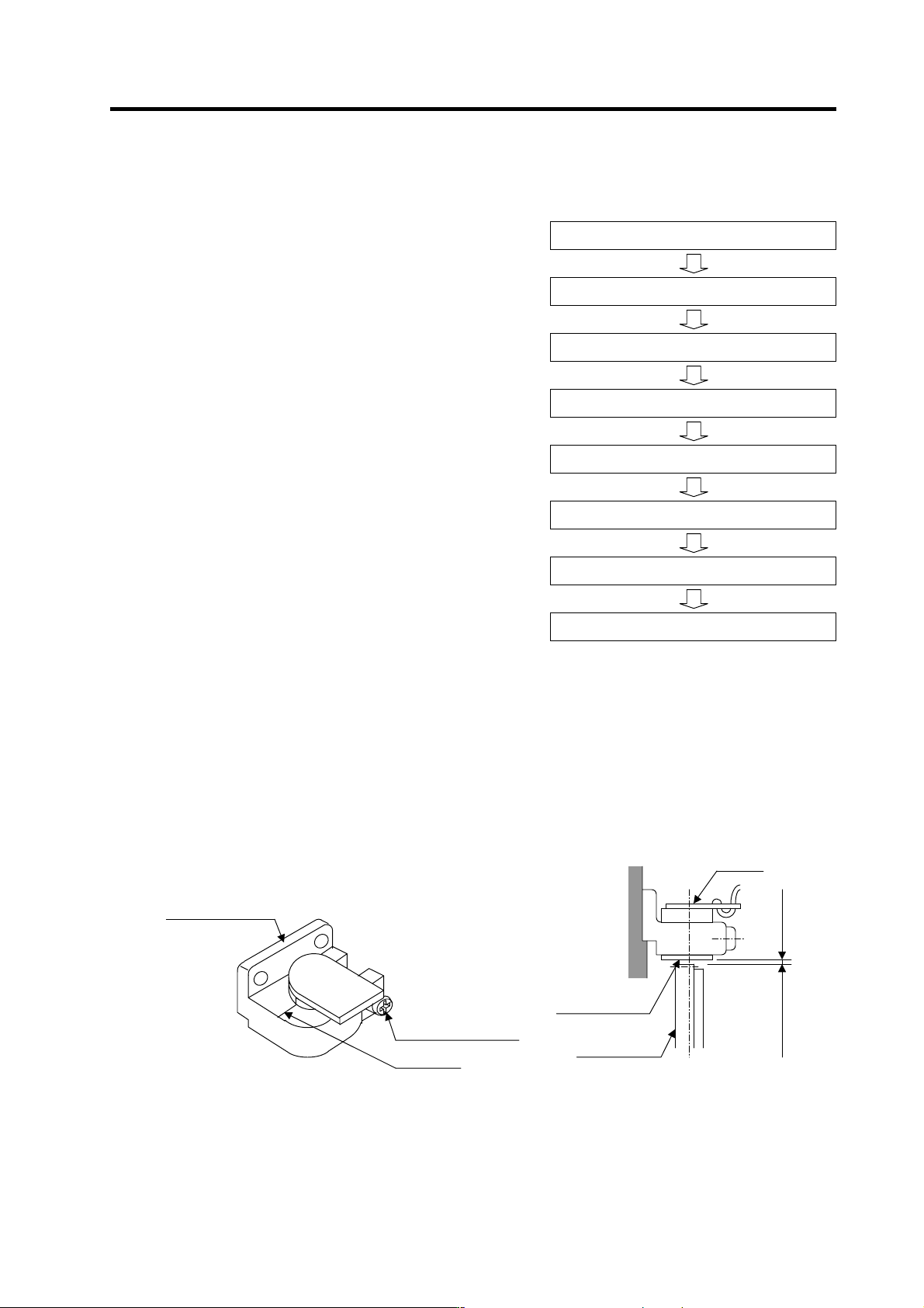
(1) Checking the gap
Check that the gap between the sensor detection surface and detection gear circumference is
within 0.15±0.01mm as shown below. The gap is adjusted before shipment, but an error could
occur due to the effect of the dimensional difference of the notched fitting section provided for
installation, or the dimensional difference of the detection gears' outer diameter. If deviated from
the above range, adjust the gap following the section "(2) Adjusting the gap".
Sensor section Gap with detection gear
(1) Checking the gap
(2) Adjusting the gap
(3) Checking the A and B phase output signal
(4) Adjusting the A and B phase output signal
(5) Checking the Z phase pulse width
(6) Adjusting the Z phase pulse width
(7) Checking the Z phase and A phase difference
(8) Adjusting the Z phase and A phase difference
Flow of PLG installation and adjustment
Senso
r
Detection gear
circumference
Ga
p
0.15±0.01mm
Detection gear
Sensor detection
surface
Markin
g
line
Sensor installation
seat
Sensor fixing screw