MDS-C1-SPA Series INSTRUCTION MANUALib1500152(eng)a.pdf - 第212页
A3 - 1 Appendix 3. EMC Installation Guidelines Appendix 3-1 Introduc tion ..................................................................................................... ................. A3-2 Appendix 3-2 EMC inst…
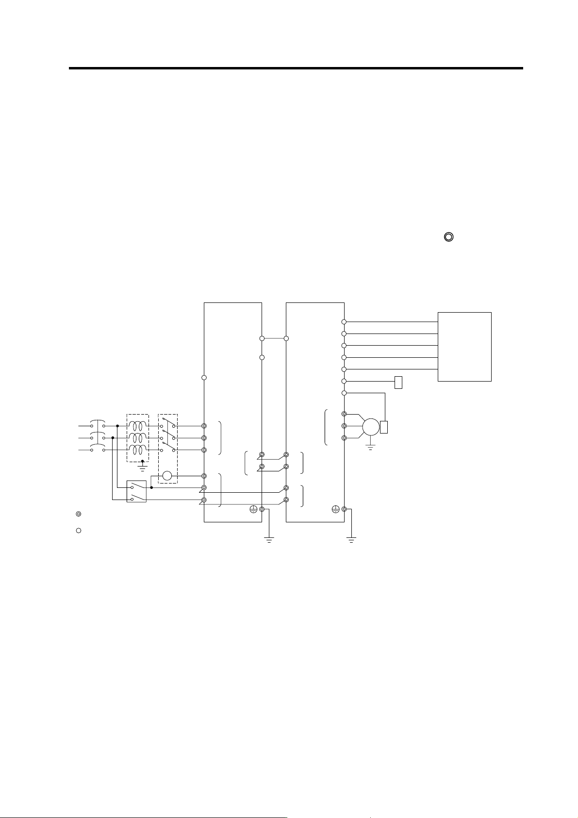
Appendix 2. Compliance to EC Directives
A2 - 4
(6) Peripheral devices
[1] Use EN/IEC Standards compliant parts for the circuit breaker and contactor.
[2] Select circuit breaker with instantaneous trip function. (Trip within 30 second when over
current of 600%). Apply Annex C of EN60204-1 for sizing of the circuit breaker.
(7) Miscellaneous
[1] Refer to the next section "EMC Installation Guidelines" for methods on complying with the
EMC Directives.
[2] Ground the facility according to each country's requirements.
[3] The control circuit connector ({) is safely separated from the main circuit (
).
[4] Inspect the appearance before installing the unit. Carry out a performance inspection of the
final unit, and save the inspection records.
MC1
External emergency stop input
T
S
R
Contacto
r
No-fuse
breaker
Ground
: Main circuit
: Control circuit
CN23
CN4
L1
L2
L3
L11
TE3
TE1
CN9
CN12
L+
L-
U
V
W
CN6
CN5
TE1
PLG
Spindle drive unitPower supply unit
Spindle
motor
CN4
TE3
TE2
L+
L-
L11
L21
TE2
AC
reactor
Ground
Ground
L21
CN9A
CN8A
MC
Breake
r
CN11
CN10
ENC
Spindle side detector
S-analog speed command, pulse feedback
Speed
•
load meter, serial I/F
Digital speed command,
general-purpose
•
error output
Orientation position command,
General-purpose output
General purpose, general-purpose output
NC
PC
DIO
Meter
Personal compu te
r

A3 - 1
Appendix 3. EMC Installation Guidelines
Appendix 3-1 Introduction ......................................................................................................................A3-2
Appendix 3-2 EMC instructions ..............................................................................................................A3-2
Appendix 3-3 EMC measures ................................................................................................................A3-3
Appendix 3-4 Measures for panel structure ...........................................................................................A3-3
Appendix 3-4-1 Measures for control panel unit.................................................................................A3-4
Appendix 3-4-2 Measures for door .....................................................................................................A3-4
Appendix 3-4-3 Measures for operation board panel .........................................................................A3-5
Appendix 3-4-4 Shielding of the power supply input section..............................................................A3-5
Appendix 3-5 Measures for various cables ............................................................................................A3-6
Appendix 3-5-1 Measures for wiring in panel .....................................................................................A3-6
Appendix 3-5-2 Measures for shield treatment...................................................................................A3-6
Appendix 3-5-3 Spindle motor power cable........................................................................................A3-7
Appendix 3-5-4 Servo motor feedback cable .....................................................................................A3-7
Appendix 3-5-5 Spindle motor power cable........................................................................................A3-8
Appendix 3-5-6 Spindle motor feedback cable...................................................................................A3-8
Appendix 3-6 EMC countermeasure parts .............................................................................................A3-9
Appendix 3-6-1 Shield clamp fitting ....................................................................................................A3-9
Appendix 3-6-2 Ferrite core ..............................................................................................................A3-10
Appendix 3-6-3 Power line filter........................................................................................................A3-11
Appendix 3-6-4 Surge protector........................................................................................................A3-16

Appendix 3. EMC Installation Guidelines
A3 - 2
Appendix 3-1 Introduction
EMC Instructions became mandatory as of January 1, 1996. The subject products must have a CE mark
attached indicating that the product complies with the Instructions.
As the NC unit is a component designed to control machine tools, it is believed to be out of the direct
EMC Instruction subject. However, we would like to introduce the following measure plans to backup
EMC Instruction compliance of the machine tool as the NC unit is a major component of the machine
tools.
[1] Methods for installation in control/operation panel
[2] Methods of wiring cable outside of panel
[3] Introduction of countermeasure parts
Mitsubishi is carrying out tests to confirm the compliance to the EMC Standards under the environment
described in this manual. However, the level of the noise will differ according to the equipment type and
layout, control panel structure and wiring lead-in, etc. Thus, we ask that the final noise level be
confirmed by the machine manufacturer.
These contents are the same as the EMC INSTALLATION GUIDELINES (BNP-B8582-45).
For measures for CNC, refer to "EMC INSTALLATION GUIDELINES" (BNP-B2230).
Appendix 3-2 EMC instructions
The EMC Instructions regulate mainly the following two withstand levels.
Emission ..... Capacity to prevent output of obstructive noise that adversely affects external
sources.
Immunity ..... Capacity not to malfunction due to obstructive noise from external sources.
The details of each level are classified as Table 1. It is assumed that the Standards and test details
required for a machine are about the same as these.
Table 1
Class Name Details
Generic
Standard
Standards for
determining test
and measurement
Radiated noise Electromagnetic noise radiated through the air
Emission
Conductive noise Electromagnetic noise discharged from power line
EN61000-6-4
EN61800-3
(Industrial
environment
)
EN55011
Static electricity
electrical discharge
Example) Withstand level of discharge of
electricity charged in a human body.
IEC61000-4-2
Radiated magnetic
field
Example) Simulation of immunity from digital
wireless transmitters
IEC61000-4-3
Burst immunity
Example) Withstand level of noise from relays or
connecting/disconnecting live wires
IEC61000-4-4
Conductive
immunity
Example) Withstand level of noise entering
through power line, etc.
IEC61000-4-6
Power supply
frequency field
Example) 50/60Hz power frequency noise
IEC61000-4-8
Power dip
(fluctuation)
Example) Power voltage drop withstand level
IEC61000-4-11
Immunity
Surge
Example) Withstand level of noise caused by
lightning
EN61000-6-2
EN61800-3
(Industrial
environment)
IEC61000-4-5