MDS-C1-SPA Series INSTRUCTION MANUALib1500152(eng)a.pdf - 第16页
1 - 1 1. Installation 1-1 Installation of spindle motor ............................................................................................. .................. 1-2 1-1-1 Environm ental c onditions ..............…

Contents for MDS-C1-SPA Series SPECIFICATIONS MANUAL (IB-1500150)
Appendix 7. EMC Installation Guidelines
Appendix 7-1 Introduction .........................................A7-2
Appendix 7-2 EMC instructions .................................A7-2
Appendix 7-3 EMC measures ...................................A7-3
Appendix 7-4 Measures for panel structure ..............A7-3
Appendix 7-4-1 Measures for control panel unit..................A7-3
Appendix 7-4-2 Measures for door...................................... A7-4
Appendix 7-4-3 Measures for operation board panel ..........A7-4
Appendix 7-4-4 Shielding of the power supply input section
..................................................................A7-4
Appendix 7-5 Measures for various cables ...............A7-5
Appendix 7-5-1 Measures for wiring in panel ...................... A7-5
Appendix 7-5-2 Measures for shield treatment....................A7-5
Appendix 7-5-3 Servomotor power cable ............................A7-6
Appendix 7-5-4 Servomotor feedback cable .......................A7-6
Appendix 7-5-5 Spindle motor power cable.........................A7-7
Appendix 7-5-6 Spindle motor feedback cable....................A7-7
Appendix 7-6 EMC countermeasure parts ................A7-8
Appendix 7-6-1 Shield clamp fitting.....................................A7-8
Appendix 7-6-2 Ferrite core ................................................A7-9
Appendix 7-6-3 Power line filter .......................................... A7-10
Appendix 7-6-4 Surge protector..........................................A7-15
Appendix 8. Instruction Manual for Compliance with UL/c-UL
Standard
Appendix 8 Instruction Manual for Compliance with UL/c-UL
Standard.................................................A8-2
Appendix 9. Compliance with China Compulsory Product
Certification (CCC Certification) System
Appendix 9-1 Outline of China Compulsory Product
Certification System ............................A9-2
Appendix 9-2 First Catalogue of Products subject to
Compulsory Product Certification........A9-2
Appendix 9-3 Precautions for Shipping Products......A9-3
Appendix 9-4 Application for Exemption ...................A9-4
Appendix 9-5 Mitsubishi NC Product Subject to/Not Subject
to CCC Certification ............................A9-5
(Note) This is the content for SPECIFICATION MANUAL version A. The structure of section and page number may be different
other than version B.

1 - 1
1. Installation
1-1 Installation of spindle motor ............................................................................................................... 1-2
1-1-1 Environmental conditions ............................................................................................................ 1-2
1-1-2 Shaft characteristics .................................................................................................................... 1-2
1-2 Installation of the control unit ............................................................................................................. 1-3
1-2-1 Environmental conditions ............................................................................................................ 1-3
1-2-2 Installation direction and clearance............................................................................................. 1-4
1-2-3 Prevention of entering of foreign matter...................................................................................... 1-4
1-2-4 Panel installation hole work drawings (Panel cut drawings) ....................................................... 1-5
1-2-5 Heating value .............................................................................................................................. 1-6
1-2-6 Heat radiation countermeasures ................................................................................................. 1-7
1-3 Installing the spindle detector............................................................................................................. 1-9
1-3-1 Magnetic sensor .......................................................................................................................... 1-9
1-3-2 Spindle side detector................................................................................................................. 1-11
1-4 Noise measures ............................................................................................................................... 1-12
1. Installation
1 - 2
1-1 Installation of spindle motor
CAUTION
1. Do not hold the cables, axis or detector when transporting the motor. Failure to
observe this could lead to faults or injuries.
2. Securely fix the motor to the machine. Insufficient fixing could lead to the
motor deviating during operation. Failure to observe this could lead to
injuries.
3. When coupling to a servomotor shaft end, do not apply an impact by
hammering, etc. The detector could be damaged.
4. Never touch the rotary sections of the motor during operations. Install a
cover, etc., on the shaft.
5. Do not apply a load exceeding the tolerable load onto the servomotor shaft.
The shaft could break. Failure to observe this could lead to injuries.
6. Do not connect or disconnect any of the connectors while the power is ON.
1-1-1 Environmental conditions
Environment Conditions
Ambient temperature 0°C to +40°C (with no freezing)
Ambient humidity 90%RH or less (with no dew condensation)
Storage temperature -20°C to +65°C (with no freezing)
Storage humidity 90%RH or less (with no dew condensation)
At mosphere
Indoors (Where unit is not subject to direct sunlight)
No corrosive gases, flammable gases, oil mist or dust
Altitude
Operation/storage: 1000m or less above sea level
Transportation: 10000m or less above sea level
(Note) Refer to each spindle motor specifications for details on the spindle motor vibration conditions.
1-1-2 Shaft characteristics
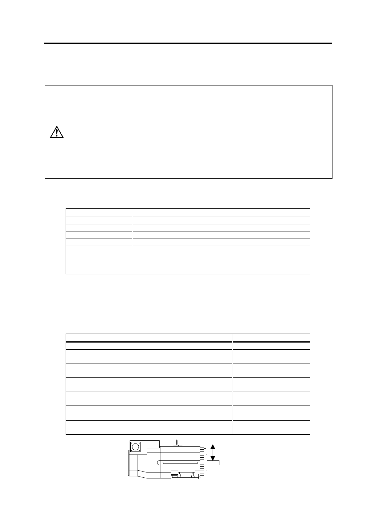
There is a limit to the load that can be applied on the motor shaft. Make sure that the load applied on the
radial direction, when mounted on the machine, is below the tolerable values given below. These loads
also affect the motor output torque, so consider them when designing the machine.
Spindle motor Tolerable radial load
SJ-V3.7-02ZM 490 N
SJ-V2.2-01, SJ-V3.7-01
SJ-V7.5-03ZM, SJ-V11-06ZM
980 N
SJ-V5.5-01, SJ-V11-08ZM
SJ-PMF01830-00
1470 N
SJ-V7.5-01, SJ-V11-01
SJ-V22-06ZM, SJ-V30-02ZM, SJ-PMF03530-00
1960 N
SJ-V11-09, SJ-V15-01, SJ-V15-03, SJ-V18.5-01, SJ-V18.5-03
SJ-V22-01, SJ-V22-05, SJ-V26-01, SJ-30A
2940 N
SJ-22XW5 3920 N
SJ-37BP 4900 N
SJ-22XW8, SJ-45BP
SJ-V55-01
5880 N
(Note) The load point is at the one-half of the shaft length.
Radial load