MDS-C1-SPA Series INSTRUCTION MANUALib1500152(eng)a.pdf - 第179页
5. Troubleshooting 5 - 8 5-3-2 Troubleshooting for each alarm No. Alarm No. 12 Memory error 1 A CPU or internal memor y error was detected during the self-check at power ON. Investigation details Investigation results Re…
5. Troubleshooting
5 - 7
5-3 Troubleshooting
Follow this section to troubleshoot the alarms that occur during start up or while the machine is
operating. If the state is not improved with the following investigations, the drive unit may be faulty.
Exchange the unit with another unit of the same capacity, and check whether the state is improved.
5-3-1 Troubleshooting at power ON
If the NC system does not start up correctly and a system error occurs when the NC power is turned
ON, the drive unit may not have been started up properly. Check the LED display on the drive unit, and
take measures according to this section.
LED
display
Symptom Cause of occurrence In vestigation m etho d Remedy
External input signal input
error
Is the alarm reset signal turned ON? Turn the signal OFF.AA The S/W did not operate
correctly when the power
was turned ON.
The alarm reset signal
was input.
The drive unit has error. Other than above Replace the drive
unit.
.
The setting is for use
inhibiting.
Is the rotary switch set to "7" to "F"? Set correctly. Ab The S/W did not operate
correctly when the power
was turned ON.
The drive unit has error. Other than above Replace the drive
unit.
Check the repeatability. Replace the unit. 12 An error was detected in
the unit's memory and IC
during the self-diagnosis
at power ON.
The CPU peripheral circuit is
abnormal.
Check whether there is any abnormality
with the unit's surrounding environment,
etc.
Improve the
surrounding
environment.
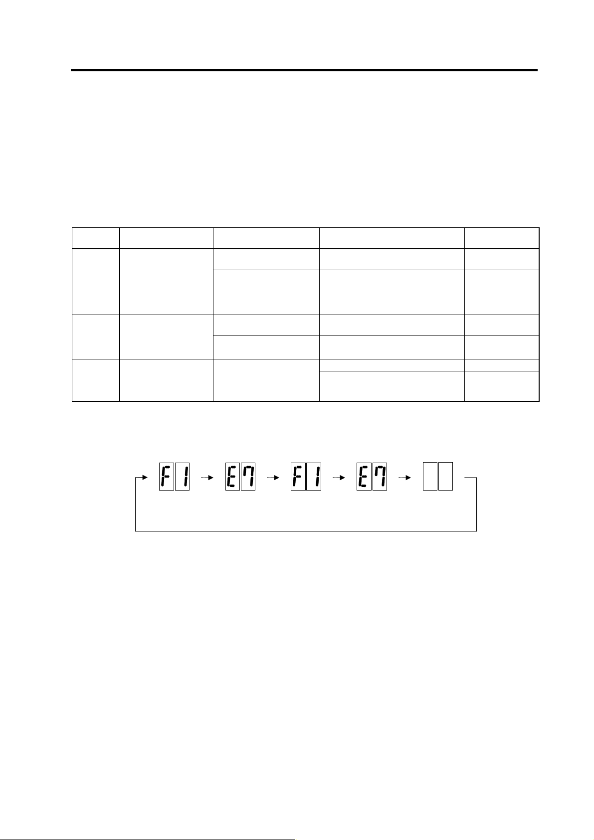
The drive unit has started up normally if the following type of emergency stop (E7) is displayed on the
display unit's LED display.
F1
F+axis No.
E7
Emergency stop
Not lit F1
F+axis No.
E7
Emergency stop
Normal drive unit LED display at power ON
5. Troubleshooting
5 - 8
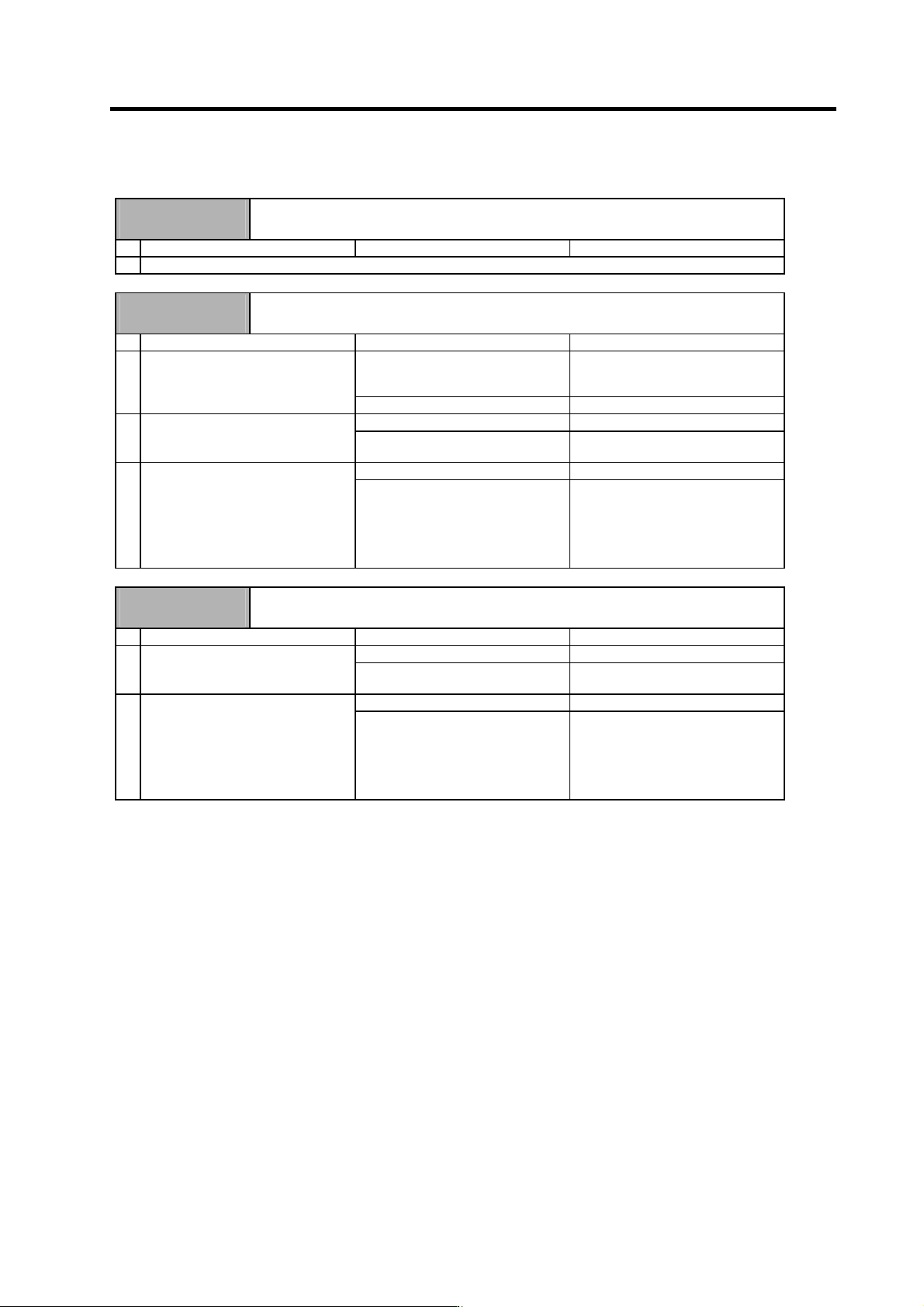
5-3-2 Troubleshooting for each alarm No.
Alarm No.
12
Memory error 1
A CPU or internal memory error was detected during the self-check at power ON.
Investigation details Investigation results Remedies
1 Refer to "5-3-1 Troubleshooting at power ON".
Alarm No.
13
Software processing error 1
The software process was not completed within the specified time. (CPU1)
Investigation details Investigation results Remedies
The version was changed. Try replacing with the drive unit
containing the original software
version.
1 Check whether the software version
was changed recently.
The version was not changed. Investigate item 2.
The error is always repeated. Replace the drive unit. 2 Check the repeatability.
The state returns to normal once, but
occurs sometimes thereafter.
Investigate item 3.
No abnormality is found in particular. Replace the drive unit. 3 Check if there is any abnormality in
the unit's ambient environment.
(Ex. Ambient temperature, noise,
grounding)
An abnormality was found in the
ambient environment.
Take remedies according to the
causes of the abnormality.
Ex. High temperature:
Check the cooling fan.
Incomplete grounding:
Additionally ground.
Alarm No.
17
A/D converter error
An error was detected in the A/D converter for current FB detection.
Investigation details Investigation results Remedies
1 The error is always repeated. Replace the drive unit.
Check the repeatability.
The state returns to normal once, but
occurs sometimes thereafter.
Investigate item 2.
2 No abnormality is found in particular. Replace the drive unit.
Check if there is any abnormality in
the unit's ambient environment.
(Ex. Ambient temperature, noise,
grounding)
An abnormality was found in the
ambient environment.
Take remedies according to the
causes of the abnormality.
Ex. High temperature:
Check the cooling fan.
Incomplete grounding:
Additionally ground.
5. Troubleshooting
5 - 9
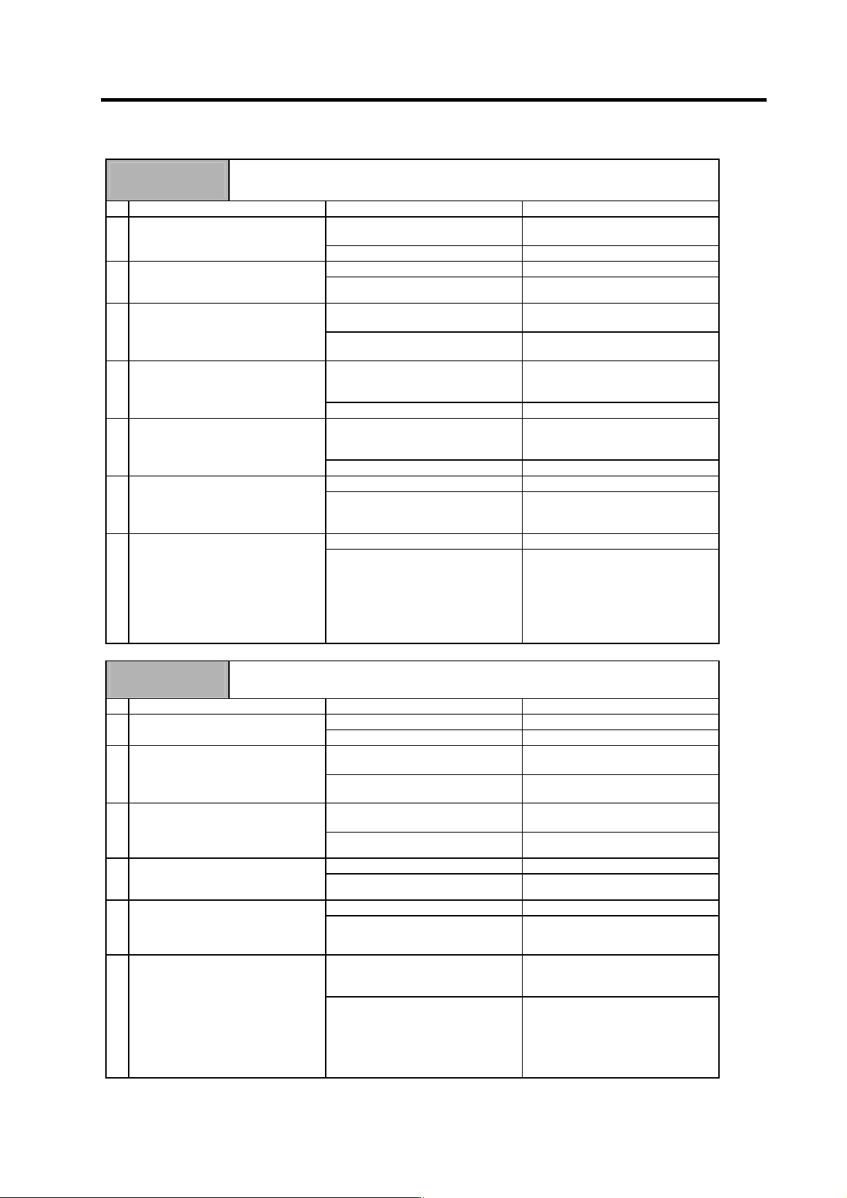
Alarm No.
20
Motor side detector, No signal 1
A PLG Z-phase no signal was detected.
An error was detected in the A/B phase output waveform during PLG automatic adjustment.
Investigation details Investigation results Remedies
The connector is disconnected (or
loose).
Correctly install. 1 Check whether the drive unit
connectors (CN5) or detector
connectors are disconnected.
The connector is not disconnected. Investigate item 2.
There is a connection fault. Replace the detector cable. 2 Turn the power OFF, and check the
detector cable connection with a
tester.
The connection is normal. Investigate item 3.
The alarm occurred during PLG
automatic adjustment.
Investigate item 4. 3 Check whether the alarm occurred
during PLG automatic adjustment.
The alarm occurred during normal
operation.
Investigate item 5.
There is a problem. (The A/B phase
input voltage is 0.8V or less or 2.2V
or higher.)
Adjust the PLG output waveform. 4 Check the PLG output waveform (A/B
phase).
Normal Investigate item 6.
There is a problem. (The output
waveform is 0V even after the gears'
Z-phase is passed.)
Investigate item 7. 5 Check the PLG output waveform
(Z-phase).
Normal Investigate item 6.
Occurs each time. Replace the drive unit. 6 Check the occurrence frequency.
Occurs occasionally. Check whether the cable is
disconnected, whether there is a
contact fault, or a detector fault.
No abnormality is found in particular. Replace the PLG detector. 7 Check if there is any abnormality in
the unit's ambient environment.
(Ex. Ambient temperature, noise,
grounding)
An abnormality was found in the
ambient environment.
Take measures according to the error
cause.
Cable disconnection, contact fault.
The sensor is hot during high-load
operation.
Review the operation, and adjust
the Z-phase again.
Alarm No.
21
Machine side detector, No signal 2
The no-signal of 1024p/rev encoder for orientation was detected.
Investigation details Investigation results Remedies
Encoder orientation is not used. Set SP037/bit0 to 0. 1 Check the spindle parameter
(SP037/bit0) setting.
Encoder orientation is used. Investigate item 3.
The gear rate does not match an
actual machine.
Correctly set the value of SP025 to
SP031.
2 Check the spindle parameter SP025
to SP031 settings.
A gear selection of sequence differs
from an actual gear.
Correctly select the gear.
The connector is disconnected (or
loose).
Correctly install. 3 Check whether the drive unit
connectors (servo: CN6, spindle:
CN6) or detector connectors are
disconnected.
The connector is not disconnected. Investigate item 4.
There is a connection fault. Replace the detector cable. 4 Turn the power OFF, and check the
detector cable connection with a
tester.
The connection is normal. Investigate item 5.
The alarm is on the drive unit side. Replace the drive unit. 5 Connect to another normal spindle
drive unit, and check whether the
fault is on the drive unit side or
detector side.
The alarm is on the detector side. Investigate item 6.
No abnormality is found in particular. Replace the detector.
(With the absolute position system,
the zero point must be established.)
6 Check if there is any abnormality in
the detector's ambient environment.
(Ex. Ambient temperature, noise,
grounding)
An abnormality was found in the
ambient environment.
Take remedies according to the
causes of the abnormality.
Ex. High temperature:
Check the cooling fan.
Incomplete grounding:
Additionally ground.