MDS-C1-SPA Series INSTRUCTION MANUALib1500152(eng)a.pdf - 第177页
5. Troubleshooting 5 - 6 5-2-2 List of warnings When a warning occurs, a warning No. will appear on the NC mo nitor screen and with the LEDs on the front of the drive unit. Check the warning No., and re move the cause of…
5. Troubleshooting
5 - 5
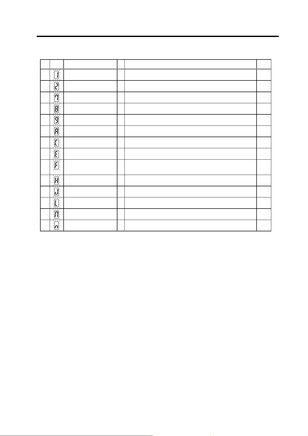
Power supply alarm
No.
LED
display
Alarm name SP Alarm details Reset
61
Power module overcurrent
§
The power module's overcurrent protection function activated. PR
62
Frequency error
§
The input power frequency exceeded the specified range. PR
67
Phase failure
§
There is a phase failure in the input power. PR
68
Watch dog
§
The system is not operating normally. AR
69
Ground fault
§
The motor power cable is contacting FG (ground). PR
6A
External contactor melting
§
The external contactor's contact has melted. PR
6C
Main circuit error
§
An abnormality was detected in the main circuit capacitor's charging
operation.
PR
6E
Memory error
§
An error was detected in the internal memory. AR
6F
Power supply error
§
The power supply is not connected, or an error was detected in the
power supply's A/D converter.
This is detected simultaneously if another power supply alarm occurs.
AR
71
Instantaneous power failure/
external emergency stop
§
An instantaneous power failure occurred. NR
73
Over-regeneration
§
The over-regeneration detection level exceeded 100%. The
regenerative resistor is in the overload state.
PR
75
Overvoltage
§
The main circuit PN bus voltage exceeded the tolerable value. NR
76
External emergency stop
setting error
§
The rotary switch setting for the external emergency stop does not
match the parameter setting.
AR
77
Power module overheat
§
The power module's temperature protection function activated. AR
(Note 1) If a power supply alarm (60 to 77) occurs, all spindles will be stop with the coast to a stop.
(Note 2) "b", "C" and "d" displayed on the power supply unit's LED as a solid light (not flickering) do not indicate an alarm.
Resetting methods
PR: Reset by setting the alarm reset signal to the general-purpose input of the spindle drive unit and turning the signal ON/OFF.
This alarm can also be reset with the AR resetting conditions.
AR: Reset by turning the spindle drive unit power ON again.
5. Troubleshooting
5 - 6
5-2-2 List of warnings
When a warning occurs, a warning No. will appear on the NC monitor screen and with the LEDs on the
front of the drive unit. Check the warning No., and remove the cause of the warning by following this
list.
Drive unit warnings
No. Alarm name Warning details Reset
A9 Orientation feedback error warn Retrying during an orientation feedback error. *
E1 Overload warning The overload detection level is 80% or more. *
E4 Parameter error warning A parameter exceeding the setting range was set. *
E7 In emergency stop state Emergency stop was input. *
(Note 1) Spindle motor does not stop when the warning occurs.
(Note 2) When an emergency stop is input, spindle motor decelerates to a stop. However, if the machine ready complete input
signal remains ON, the operation after a stop differs according to the SP192 setting.
SP192=0 or 1: After a stop. the external contactor of CV is turned OFF after a period of time.
SP192=2 or 3: The external contactor of CV has been turned ON after a stop.
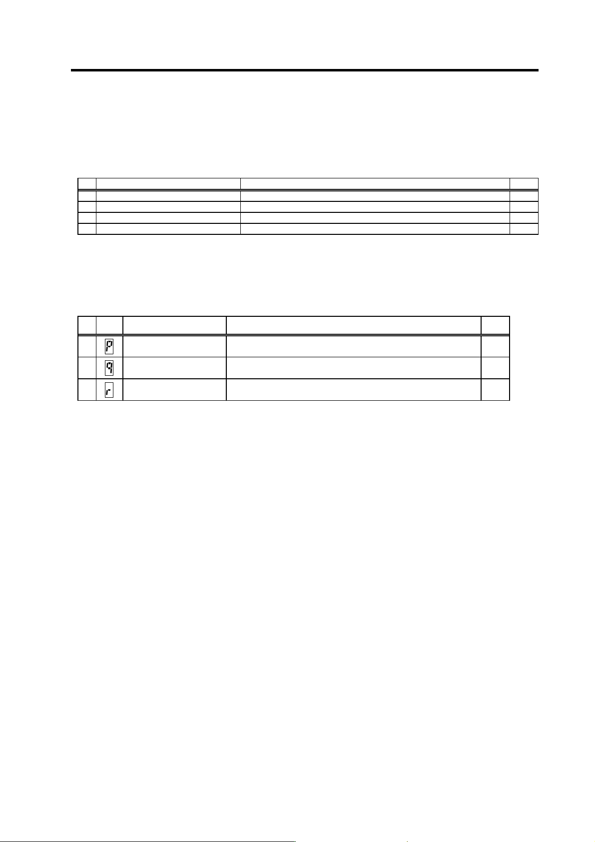
Power supply warnings
No.
LED
display
Alarm name Warning details Reset
E9
Instantaneous power failure
warning
An instantaneous power failure occurred. PR
EA
External emergency stop The external emergency stop signal was input. *
EB
Over-regeneration warning The over-regeneration level is 80% or more. *
(Note) Spindle motor does not stop when the warning occurs.
Resetting methods
* : Automatically reset once the cause of the warning is removed.
PR : Reset by setting the alarm reset signal to the general-purpose input of the spindle drive unit and turning the signal ON/OFF.
This alarm can also be reset with the AR resetting conditions.
5. Troubleshooting
5 - 7
5-3 Troubleshooting
Follow this section to troubleshoot the alarms that occur during start up or while the machine is
operating. If the state is not improved with the following investigations, the drive unit may be faulty.
Exchange the unit with another unit of the same capacity, and check whether the state is improved.
5-3-1 Troubleshooting at power ON
If the NC system does not start up correctly and a system error occurs when the NC power is turned
ON, the drive unit may not have been started up properly. Check the LED display on the drive unit, and
take measures according to this section.
LED
display
Symptom Cause of occurrence In vestigation m etho d Remedy
External input signal input
error
Is the alarm reset signal turned ON? Turn the signal OFF.AA The S/W did not operate
correctly when the power
was turned ON.
The alarm reset signal
was input.
The drive unit has error. Other than above Replace the drive
unit.
.
The setting is for use
inhibiting.
Is the rotary switch set to "7" to "F"? Set correctly. Ab The S/W did not operate
correctly when the power
was turned ON.
The drive unit has error. Other than above Replace the drive
unit.
Check the repeatability. Replace the unit. 12 An error was detected in
the unit's memory and IC
during the self-diagnosis
at power ON.
The CPU peripheral circuit is
abnormal.
Check whether there is any abnormality
with the unit's surrounding environment,
etc.
Improve the
surrounding
environment.
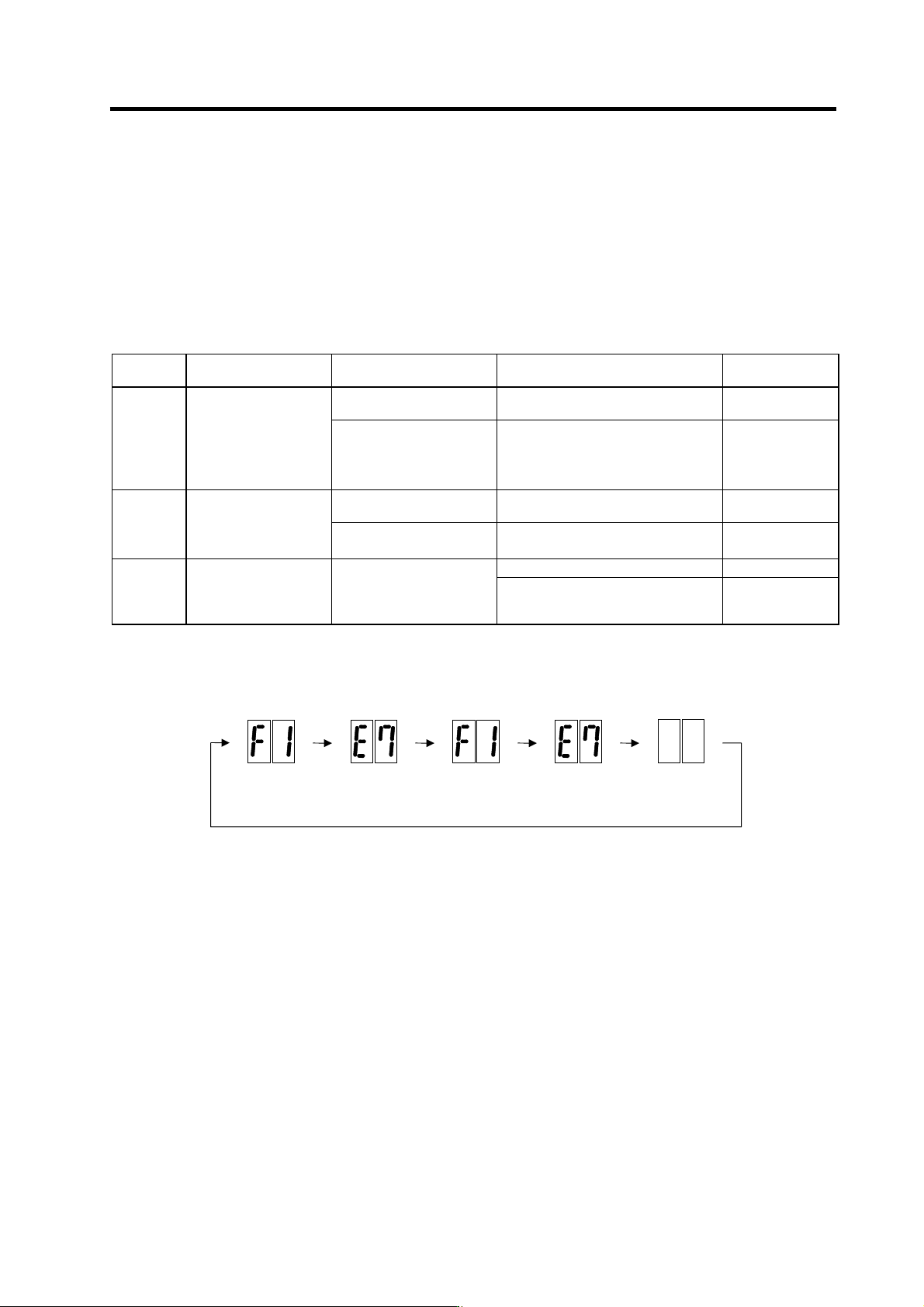
The drive unit has started up normally if the following type of emergency stop (E7) is displayed on the
display unit's LED display.
F1
F+axis No.
E7
Emergency stop
Not lit F1
F+axis No.
E7
Emergency stop
Normal drive unit LED display at power ON