MDS-C1-SPA Series INSTRUCTION MANUALib1500152(eng)a.pdf - 第152页
4. Spindle Adjustment 4 - 61 (6) Adjusting the indexing speed When "1" is set in SP0 97(SPECO) bit 4, the indexing speed is the value set in SP115(OSP2). Carry out indexing operations and a djust to t he desira…
4. Spindle Adjustment
4 - 60
(5) Adjusting the orientation control
Execute the section "4-3-3 Adjusting the orientation control". At this time, if the orientation stop
position deviates near the target stop position even if the speed loop gain during orientation
(SP098, SP099) is increased within the range that is free from vibration, change the orientation
stop control to the PI control. Furthermore, if the stop position deviates in the forwar d reverse run
even if changed to the PI control, set so that the orientation dire ction is unidirectional.
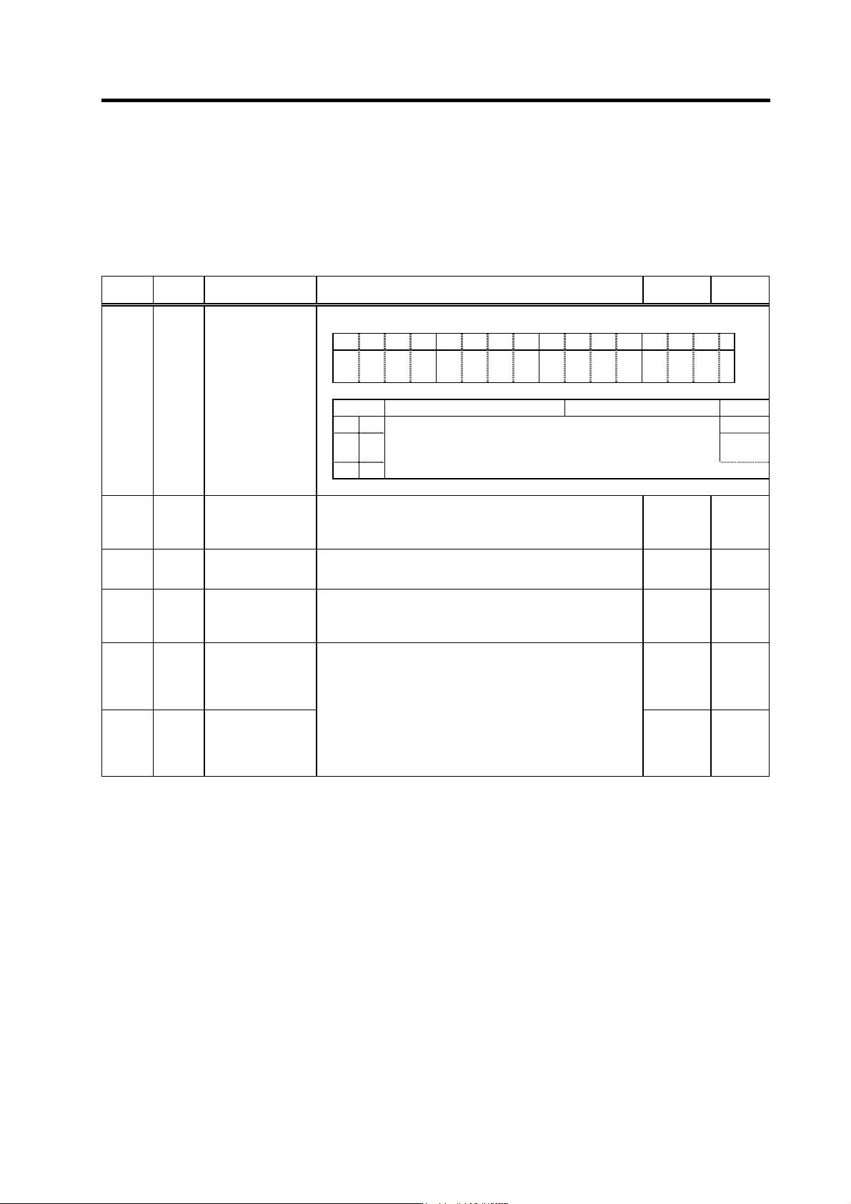
No. Abbrev. Parameter name Description
Setting
range
Standard
value
SP097 SPECO
Orientation
specification
F EDCBA98765 4 3 2 10
ostp
orze ksft gchg
ips2 zdir vg8x mdir fdir oscl
pyfx dmin
odi2 odi
1
bit Meaning when "0" is set Meaning when "1" is set Standard
0
odi1 Orientation rotation direction
0
1
odi2
00: Previous (the direction in which the motor has so far rotated under
speed control)
0
10: Backward rotation 01: Forward rotation 11: Prohibited
SP098 VGOP
Speed loop gain
proportional term in
orientation control
mode
Set the speed loop proportional gain in orientation control
mode.
When the gain is increased, rigidity is improved in the
orientation stop but vibration and sound become larger.
0 to 1000 63
SP099
VGOI
Orientation control
mode speed loop
gain integral term
Set the speed loop integral gain in orientation control mode.
0 to 1000 60
SP100
VGOD*
Orientation control
mode speed loop
gain delay advance
term
Set a loop gain delay advance gain in orientation control
mode.
When this parameter is set to "0", PI control is applied.
0 to 1000 15
SP227 OXVKP*
Speed loop
proportional gain
magnification after
orientation
completed
0 to 2560
(1/256-fold)
0
SP228 OXVKI*
Speed loop
cumulative gain
magnification after
orientation
completed
If gain changeover is valid (SP097: SPEC0/bitC=1) during
orientation control, set the magnification of speed gain
changed to after orientation completed.
0 to 2560
(1/256-fold)
0
4. Spindle Adjustment
4 - 61
(6) Adjusting the indexing speed
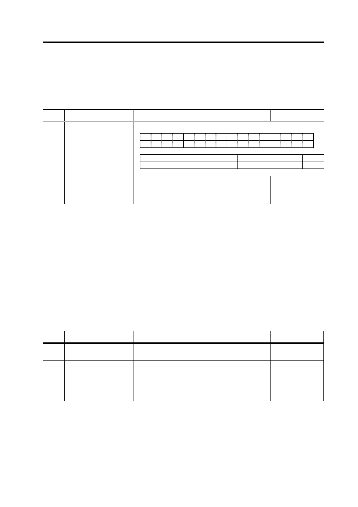
When "1" is set in SP097(SPECO) bit 4, the indexing speed is the value set in SP115(OSP2).
Carry out indexing operations and adjust to the desirable speed. Swaying may occur when
stopped as speed is increased. Note that the actual indexing speed could be smaller than the
value set in SP115 and may not be changed in 1r/min increme nts.
No. Abbrev. Parameter name Description
Setting
range
Standard
value
SP097 SPECO
Orientation control
specification
F E D C B A 9 8 7 6 5 4 3 2 1 0
ostp orze ksft gchg ips2 zdir vg8x mdir fdir oscl pyfx dmin odi2 odi1
bit Meaning when "0" is set Meaning when "1" is set Standard
4 oscl
Indexing speed clamp invalid Indexing speed clamp valid 0
SP115 OSP2
Orientation control
speed clamp value
2
When the orientation clamp speed is changed by the control
input, this parameter setting will be used instead of SP005:
OSP.
Indexing speed clamp valid
This parameter is used when (SP097: SPEC0/bit4 = 1).
0 to 32767
(r/min)
0
(7) Adjustment during index stop
With the machine in which attachments are identified, when inertia or friction torque differs from
one applied during regular orientation control, servo rigidity after completion of indexing is set
again. Refer to the item "(5) Adjustments durin g orientation stop" in the se ction "4-3-3 Adjusting the
orientation control" when setting.
(8) Adjusting the indexing complete signal
When the completion of indexing is substituted with the orientation completion signal (ORCA), if
the indexing angle or time is insufficient, indexing operation may be continued ON even if the
indexing operation is not completed. If this is an issue, use the index positioning completion signal
(WRCF). When the forward/reverse run indexing signal turns ON, the indexing completion signal
always turns OFF once and then turns ON at the completion of indexing operation. The shortest
span for the time being OFF can be set with parameters.
Related spindle parameters
No. Abbrev. Parameter name Description
Setting
range
Standard
value
SP103 FTM*
Index positioning
completion OFF
time timer
Set the time for forcedly turn OFF the index positioning
completion signal (different from the orientation completion
signal) after the rising edge of the indexing start signal.
0 to 10000
(ms)
200
SP141
to
SP154
HO1e
to
HO6c
General-purpose
output selection
open emitter 1 to
general-purpose
output selection
open collector 6
When using the index positioning completed output, set the
following value to any one of these parameters.
"2": Positioning completed (WRCF)
0 to 23 0

4. Spindle Adjustment
4 - 62
(9) Troubleshooting
For the troubles during orientation, refer to (7) Troubleshooting in the section "4-3-3 Adjusting the
orientation control".
[1] Not executing indexing operation
Cause Investigation item Remedy Remarks
1 Parameter
setting values are
incorrect
Forward/reverse run indexing start is
not set to the general-purpose input.
Or, the input in which the actual
forward/reverse run indexing signal is
wired and the location set in the
parameter are different.
Set either "2" or "3" in one of the
general-purpose input parameters
SP129 to SP140 which corresponds to
the input section where the orientation
command has been wired.
When the forward/reverse run indexing
signal is ON, the orientation command
is OFF.
To run indexing operations, always
keep the orientation command signal
turned ON.
2 Sequence error
The external stop position data has not
been changed.
Officially change the external stop
position data.
3 Incorrect wiring The connector pin numbers are
incorrect. The inserted connector
number is incorrect.
The cable is disconnected.
Correct the wiring.
Replace the cable.
[2] The motor overtravels and stops (The motor sways when stopping.)
Cause Investigation item Remedy Remarks
The selected gear and the actual gear
are different.
Adjust gear selection inputs (GR1,
GR2) according to the actual gear.
The gear ratio parameters:
SP025(GRA1) to SP032(GRB4) are
incorrect.
Correctly set SP025(GRA1) to
SP032(GRB4).
Half the deceleration rate during
orientation parameter SP006 (CSP) to
solve the problem.
Readjust SP006(CSP). This also applies
to:
SP107(CSP2)
SP108(CSP3)
SP109(CSP4)
SP121(MPCSH)
SP122(MPCSL)
1 Parameter
setting values are
incorrect
Position loop gain parameter
Change the value of SP001(PGM),
SP002(PGE) to solve the problem.
Readjust SP001(PGM), SP002(PGE). This also applies
to:
SP119(MPGH)
SP120(MPGL)
[3] The stopping position deviates
Cause Investigation item Remedy Remarks
There is backlash or slipping between
the spindle and encoder.
The gear ratio between the spindle and
encoder is not 1:1 or 1:2.
For spindle side
detector
orientation
1 Mechanical
cause
The stopping position is not deviated
with the encoder axis.
There is backlash or slipping between
the spindle and motor.
The gear ratio between the spindle and
motor is not 1:1.
For motor PLG
orientation
The position detector's cable is
relayed with a terminal block
(connector), etc.
Do not relay the cable.
The position detector cable's shield is
not treated properly.
Properly treat the shield.
2 Noise
The peeled section of signal wire at
the position detector cable's connector
section is large. (A large section is not
covered by the shield.)
Keep the peeled section to 3cm or less
when possible. Keep the peeled section
as far away from the power cable as
possible.