MDS-C1-SPA Series INSTRUCTION MANUALib1500152(eng)a.pdf - 第211页
Appendix 2. Compliance to EC Directives A2 - 4 (6) Peripheral devices [1] Use EN/IEC Standards compliant parts for the circuit breaker and contactor. [2] Select circuit breaker with instantaneous tr ip function. (Trip wi…
Appendix 2. Compliance to EC Directives
A2 - 3
(3) Power supply
[1] Use the power supply and servo/spindle drive unit under an Overvoltage Category II as
stipulated in IEC60664.
[2] In case of Overvoltage Category III, connect the PE terminal of the units to the earthed-neutral
of the star-connection power supply system.
[3] Do not omit the circuit breaker and electromagnetic contactor.
(4) Earthing
[1] To prevent electric shocks, always connect the servo/spindle drive unit protective earth (PE)
terminal (terminal with
mark) to the protective earth (PE) on the control panel.
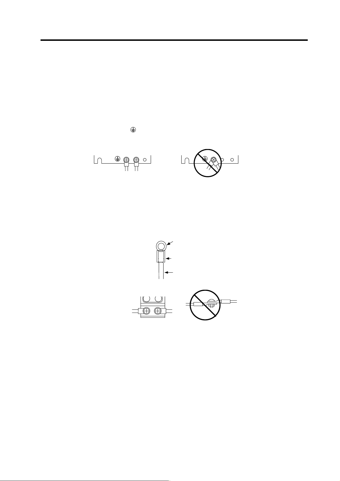
[2] When connecting the earthing wire to the protective earth (PE) terminal, do not tighten the
wire terminals together. Always connect one wire to one terminal.
PE terminal
PE terminal
[3] Select the earthing wire size in accordance with Table 1 of EN60204-1.
(5) Wiring
[1] Always use crimp terminals with insulation tubes so that the connected wire does not contact
the neighboring terminals.
Crim p termi nal
Insul ation tube
Wire
[2] Do not connect the wires directly.
[3] Select the size of the wires for input power supply to Power Supply unit in accordance with
Table 4 and 5 of EN60204-1.
Appendix 2. Compliance to EC Directives
A2 - 4
(6) Peripheral devices
[1] Use EN/IEC Standards compliant parts for the circuit breaker and contactor.
[2] Select circuit breaker with instantaneous trip function. (Trip within 30 second when over
current of 600%). Apply Annex C of EN60204-1 for sizing of the circuit breaker.
(7) Miscellaneous
[1] Refer to the next section "EMC Installation Guidelines" for methods on complying with the
EMC Directives.
[2] Ground the facility according to each country's requirements.
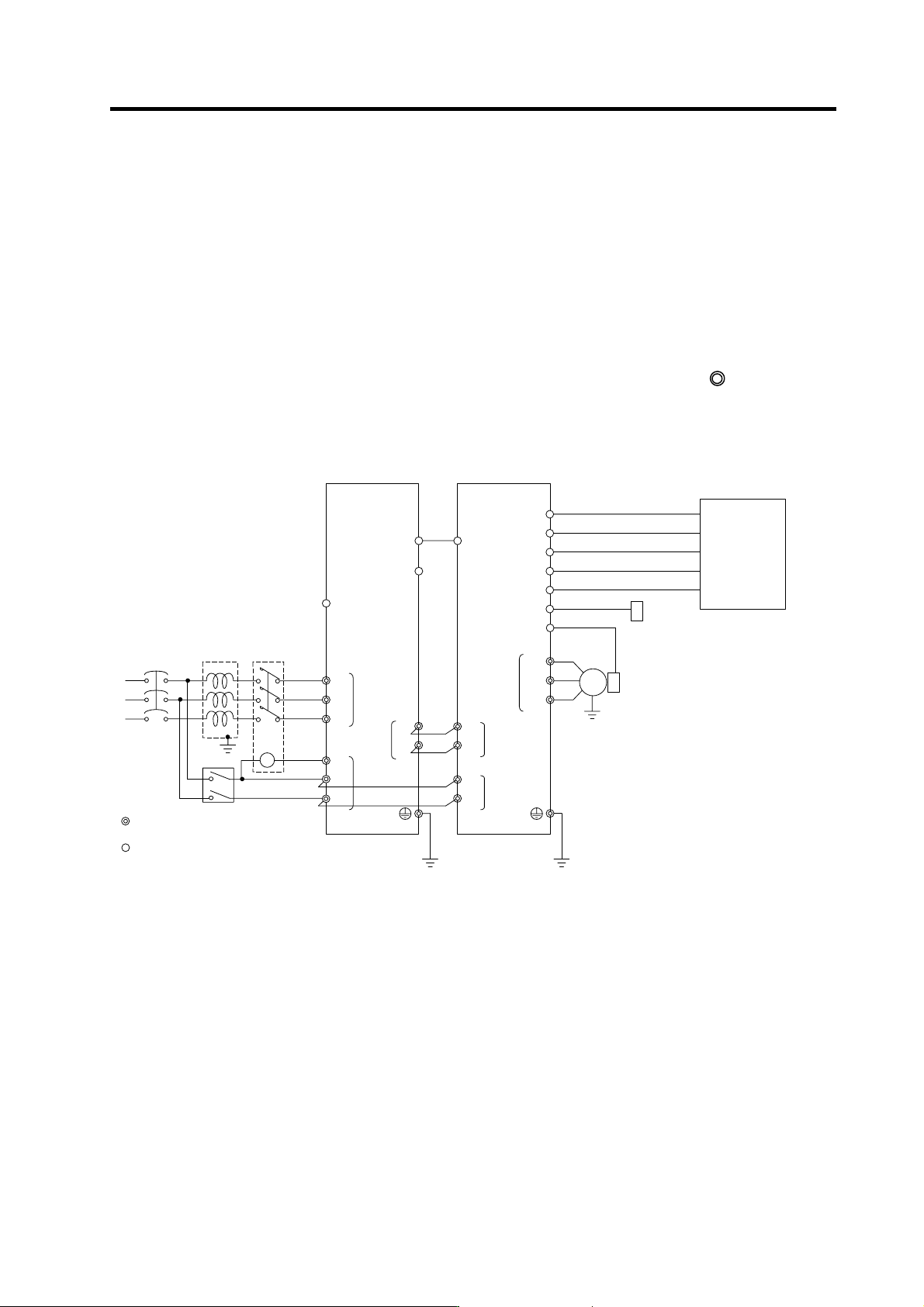
[3] The control circuit connector ({) is safely separated from the main circuit (
).
[4] Inspect the appearance before installing the unit. Carry out a performance inspection of the
final unit, and save the inspection records.
MC1
External emergency stop input
T
S
R
Contacto
r
No-fuse
breaker
Ground
: Main circuit
: Control circuit
CN23
CN4
L1
L2
L3
L11
TE3
TE1
CN9
CN12
L+
L-
U
V
W
CN6
CN5
TE1
PLG
Spindle drive unitPower supply unit
Spindle
motor
CN4
TE3
TE2
L+
L-
L11
L21
TE2
AC
reactor
Ground
Ground
L21
CN9A
CN8A
MC
Breake
r
CN11
CN10
ENC
Spindle side detector
S-analog speed command, pulse feedback
Speed
•
load meter, serial I/F
Digital speed command,
general-purpose
•
error output
Orientation position command,
General-purpose output
General purpose, general-purpose output
NC
PC
DIO
Meter
Personal compu te
r

A3 - 1
Appendix 3. EMC Installation Guidelines
Appendix 3-1 Introduction ......................................................................................................................A3-2
Appendix 3-2 EMC instructions ..............................................................................................................A3-2
Appendix 3-3 EMC measures ................................................................................................................A3-3
Appendix 3-4 Measures for panel structure ...........................................................................................A3-3
Appendix 3-4-1 Measures for control panel unit.................................................................................A3-4
Appendix 3-4-2 Measures for door .....................................................................................................A3-4
Appendix 3-4-3 Measures for operation board panel .........................................................................A3-5
Appendix 3-4-4 Shielding of the power supply input section..............................................................A3-5
Appendix 3-5 Measures for various cables ............................................................................................A3-6
Appendix 3-5-1 Measures for wiring in panel .....................................................................................A3-6
Appendix 3-5-2 Measures for shield treatment...................................................................................A3-6
Appendix 3-5-3 Spindle motor power cable........................................................................................A3-7
Appendix 3-5-4 Servo motor feedback cable .....................................................................................A3-7
Appendix 3-5-5 Spindle motor power cable........................................................................................A3-8
Appendix 3-5-6 Spindle motor feedback cable...................................................................................A3-8
Appendix 3-6 EMC countermeasure parts .............................................................................................A3-9
Appendix 3-6-1 Shield clamp fitting ....................................................................................................A3-9
Appendix 3-6-2 Ferrite core ..............................................................................................................A3-10
Appendix 3-6-3 Power line filter........................................................................................................A3-11
Appendix 3-6-4 Surge protector........................................................................................................A3-16