MDS-C1-SPA Series INSTRUCTION MANUALib1500152(eng)a.pdf - 第156页
4. Spindle Adjustment 4 - 65 [Outline of operation] Turn OFF the start comma nd for forward run, revers e run and orientation to stop the motor. Then, turn the speed command voltage to "0". After that, tu rn ON…
4. Spindle Adjustment
4 - 64
4-3-5 Adjusting S-analog high-speed tapping control
(1) Necessary input/output
I/O Signal name I/O mode Mandatory/Optional
S-analog high-speed tapping input (HSP) General-purpose input
Analog speed command input (bipolar) Analog input
Input
Forward run signal (SRN), reverse run signal (SRI) Special input
Pulse feedback output signal Special output
Up-to-speed output signal General-purpose output
Output
Zero speed output signal General-purpose output
: Mandatory
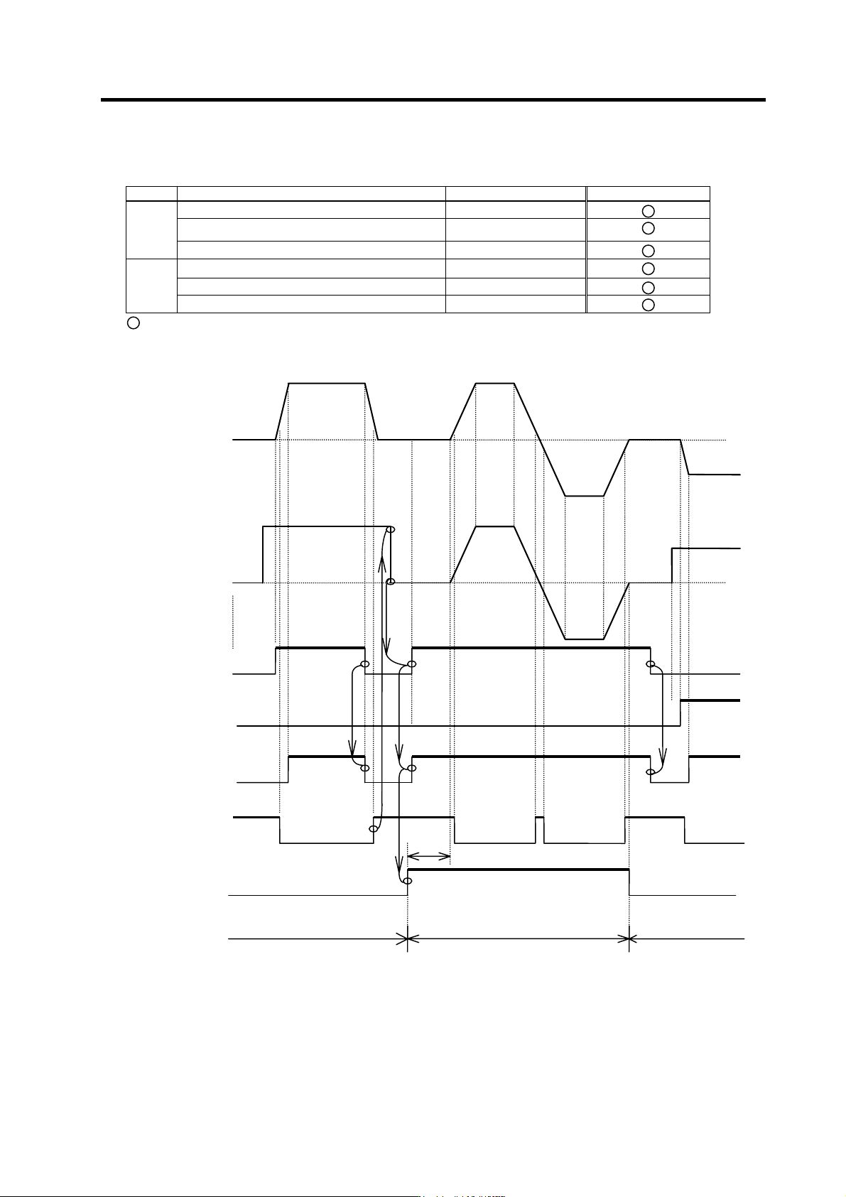
(2) Operation sequence
OFF
ON
OFF
t1
Motor speed
Forward run start
Up-to-speed
S-analog high-speed
tapping
OFF OFF
ON ON
ON
ON
ON
ON ON ON
ON
OFF
OFF
OFF
OFF
OFF
OFF
OFF
OFF
ON
O
O
S-analog speed
command voltage
Reverse run start
Zero speed
Mode
Regular speed loop Regular speed loop S-analog synchronous tapping mode
4. Spindle Adjustment
4 - 65
[Outline of operation]
Turn OFF the start command for forward run, reverse run and orientation to stop the motor. Then, turn
the speed command voltage to "0". After that, turn ON the forward run command, then the S analog
synchronous tapping com mand. Th e sp indle drive un it makes the spe ed command cu shion t o "0" whil e
S analog synchronous tapping command is ON and rotates the motor according to the given speed
command voltage. Create a position loop for the NC unit, based on A-, B-, Z-phase pulse of the pulse
feedback signal output from the spindle drive unit.
CAUTION
1. A-, B-, Z-phase pulse output from the pulse feedback output are determined
by the detector to be used for orientation and cannot be selected arbitrarily
when using this function.
2. When focusing precision while using this function, the load inertia shall be
less than 3-times the motor inertia.
3. In the case where no orientation function is available, this function can be
used even if PLG with Z phase is not mounted onto the motor. However, in
that case, Z phase signal will not be output from the pulse feedback output,
and the one-rotation position cannot be detected.
4. When inputting the speed command, always use the bipolar analog input
section. Also, set the parameters in bipolar settings.
5. When a coil changeover motor is u se d, do not turn the L-coil selection
signal ON/OFF during this control. When L-coil selection signal is turned
ON/OFF, the coil changeover operation is immedi ately executed with the
spindle drive unit, causing some failu re such as breakage of taps.
(3) Confirming the initial parameters
When using this function, NC side parameters greatly affect, as well. Refer to the NC manual and
confirm the default value settings for the NC related param eters.
<Spindle drive unit side pa rameters>
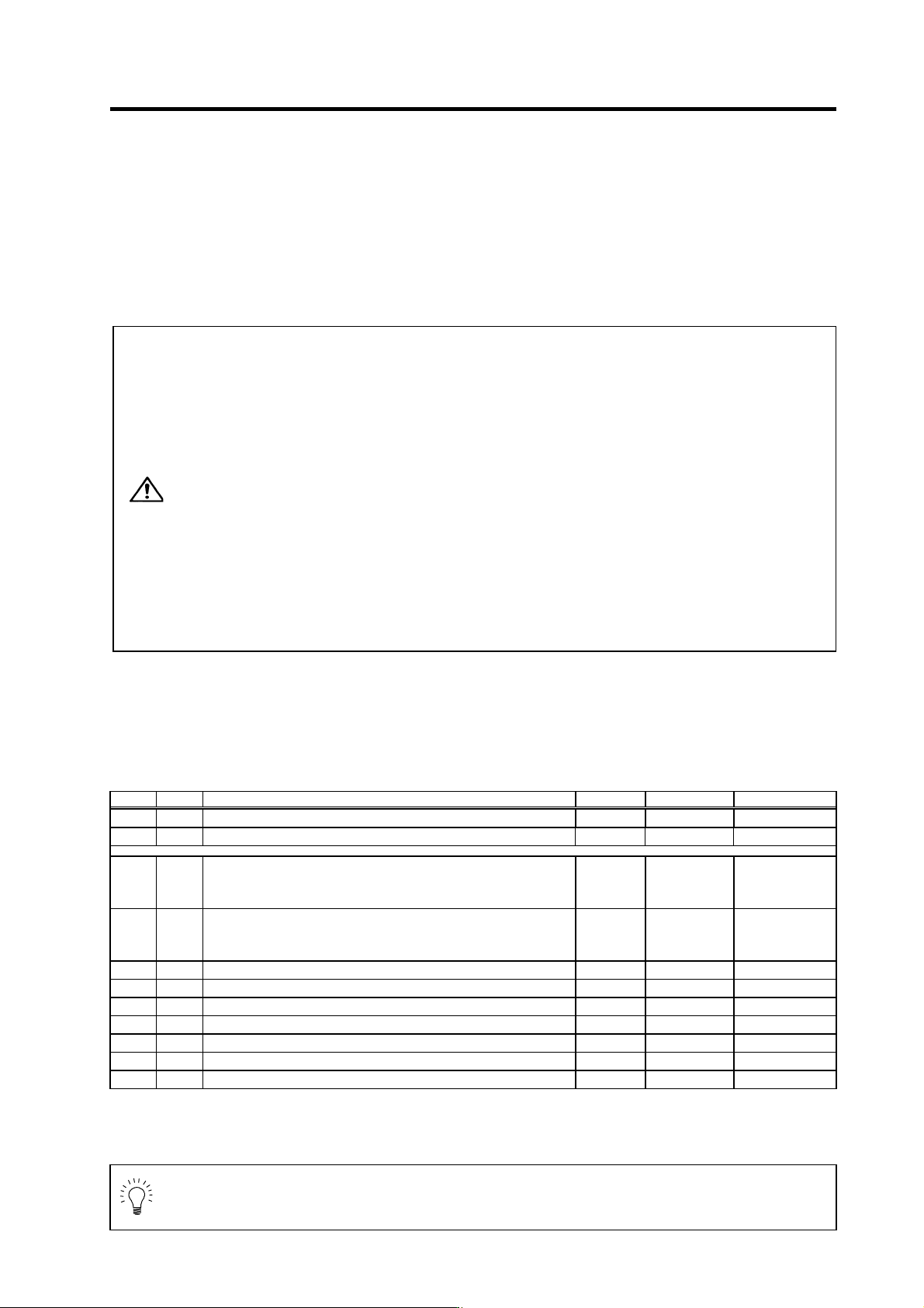
No. Abbrev. Parameter name Unit Setting range Initial value
SP037 SFNC5 Spindle function 5 - 0000 to FFFF *
SP038 SFNC6 Spindle function 6 - 0000 to FFFF *
SP129
to
SP140
HI01
to
HI12
General-purpose input selection 1 to 12 - 0 to 21
17:S-analog
high-speed
tapping
SP141
to
SP154
HO1e
to
HO6c
General-purpose output selection open emitter 1 to open collector
6
- 0 to 23
14:Up-to-speed
15:Zero speed
SP155 SAtyp S-analog speed command input type 0 to 1 0
SP171 HSPT S-analog high-speed tapping motor maximum speed r/min 0 to 32767 0
SP172 VGHP S-analog high-speed tapping speed loop proportional gain 0 to 1000 0
SP173 VGHI S-analog high-speed tapping speed loop integral gain 0 to 1000 0
SP174 HPYV S-analog high-speed tapping variable excitation rate (min value) % 0 to 100 0
SP175 HSgn* S-analog high-speed tapping speed command gain 1/1000-fold 0 to 2500 0
SP176 HADof* S-analog high-speed tapping speed command offset - -999 to 999 0
(Note 1) Symbols used in the parameter setting column
*: Set according to machine specifications, -: Setting irrelevant
(Note 2) Parameters having an abbreviation with "*" are validated right after the settings are changed by the personal computer,
without turning the spindle drive unit's power ON and OFF.
POINT
Always adjust the synchronous tap control after adjusting the operation following the
speed command and the acceleration/deceleration time, and after adjusting the
servo axis synchroni zed with the spindle during synchronous tap control.
4. Spindle Adjustment
4 - 66
(4) Adjustment
General adjustment method is described in the following. Note that, however, if the adjustment
method is described in the adjustment manual for the NC to be used, the NC adjustment manual
takes precedence over thi s manu al.
(5) Adjusting the acceleration/deceleration time constant
Synchronous tap synchronizes the operation with the servo. Generally, the spindle takes longer to
accelerate and decelerate, so the acceleration/deceleration time constant is determined on the
spindle side. Measure the acceleration time for the S command, and set a value 1.5-fold of the
measured value as the standard value.
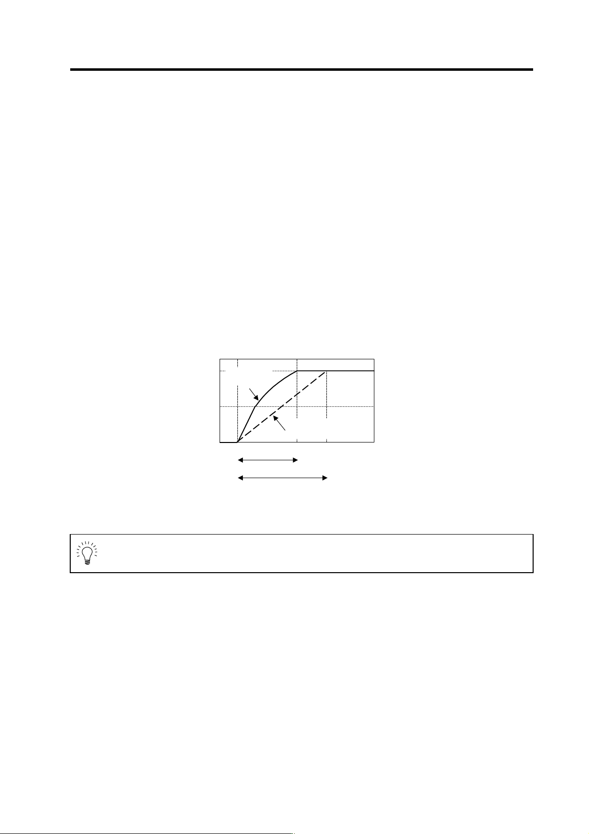
If the spindle maximum rotation speed is 2000r/min during synchronous tap operation, first carry
out 2000r/min acceleration/deceleration with the S command as shown below. Then, measure the
total acceleration time in a linear, 2-step or 3-step state. The time constant for synchronous tap
operation is 450ms which is 1.5-fold 300ms.
When the value other than "0000" is set to the spindle parameters SP314 to SP319 or SP378 to
SP383, change the parameter value as follows and turn the spindle drive unit's power ON/OFF or
turn the alarm reset input ON/OFF before collecting the acceleration/deceleration data.
Set the same value as SP314 to SP317, SP315 to SP318, and SP316 to SP319.
Set the same value as SP378 to SP381, SP379 to SP382, and SP380 to SP383.
Upon completion of the measurement, be sure to return the changed parameter value to the
original setting value.
0
1000
2000
Accelerat i on time during S command
Standard accel erati on time duri ng synchronous tap (1. 5-fold)
Measuring the acceleration time during S command
Speed FB
[r/min]
0
300 450 [ms]
During
S command
During synchronous
ta
p
control
POINT
When executing the synchronous tappin g operation with the coil changeover motor,
the coil must be fixed and used. In this case, fix all the coils to be use d one by one,
and carry out S command to measure the acceleration/deceleration time.