MDS-C1-SPA Series INSTRUCTION MANUALib1500152(eng)a.pdf - 第106页
4. Spindle Adjustment 4 - 15 4-2-2 Spindle control output (SP to NC) (1) Spindle control output 1 Name Details F E D C B A 9 8 7 6 5 4 3 2 1 0 CL TL3A TL2A TL1 A ALM PRMA WRN RON bit Details 0 RON In READY ON 1 2 3 4 WRN…
4. Spindle Adjustment
4 - 14
Related spindle parameters
No. Abbr. Parameter name Details
Setting
range
Standard
SP129
to
SP140
HI01
to
HI12
General-purpose
input selection 1
to
General-purpose
input selection 12
Set the following value in any one of these parameters when
using the digital speed command.
"15": Digital speed command valid (deg) 0 to 21 0
SP156 DGtyp
Digital speed
command input type
Set the digital speed command input method.
"0": Signed binary
"1": No sign 12-bit binary
"2": BCD2 digits
"3": BCD3 digits
0 to 3 0
bit6.Override analog input (OR1, OR2)
This signal turns ON when the override input is closed (ON: valid).
This is used apart from the speed command to change the motor rotation speed.
Note that, however, this input can be used only when the S analog speed command or digital
speed command is used, and the commanded voltage is input in the CN8A-7 pin in the case with
the S analog speed command input. This cannot be used when using the sp eed setting function.
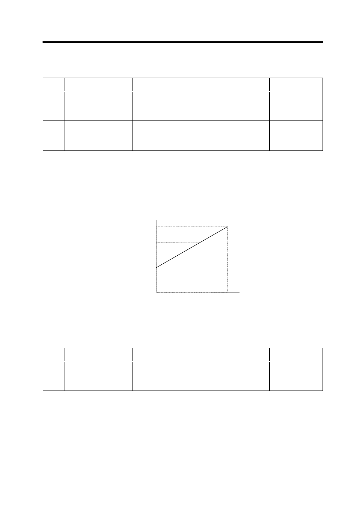
The motor speed in respect to the CN8A-17 pin (OR2) input voltage is as shown below.
Motor speed
CN8A-17 pin
Input voltage
+10V 0
(120%)
(50%)
Motor regular speed (100%)
If the speed command is Nr/min now, the speed can be changed to 0.5-1.2Nr/min with this input.
With the input of 0V, 0.5Nr/min, with +10V, 1.2Nr/min can be achiev ed.
Note that, however, the speed is clamped at the motor maximum speed setting value (parameter:
SP017(TSP)).
Related spindle parameters
No. Abbr. Parameter name Details
Setting
range
Standard
SP129
to
SP140
HI01
to
HI12
General-purpose
input selection 1
to
General-purpose
input selection 12
Set the following value in any one of these parameters when
using the override input.
"16": Override input valid (ovr)
0 to 21 0
bit7.S analog high-speed synchronous tapping
This signal turns ON when the S analog high-speed synchronous tapping input is closed (ON).
For the related parameters, refer to the section covering the adjustment procedures for each
control "adjusting S analog high-speed synchronous tapping"
4. Spindle Adjustment
4 - 15
4-2-2 Spindle control output (SP to NC)
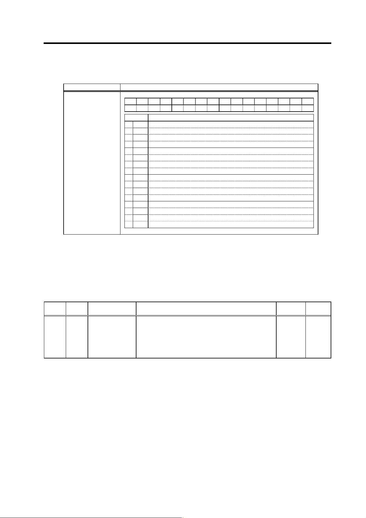
(1) Spindle control output 1
Name Details
F E D C B A 9 8 7 6 5 4 3 2 1 0
CL
TL3A TL2A TL1A
ALM
PRMA
WRN
RON
bit Details
0
RON
In READY ON
1
2
3
4
WRN
In drive unit warning
5
6
PRMA
In parameter conversion
7
ALM
In drive unit alarm
8
TL1A
In torque limit 1 signal input
9
TL2A
In torque limit 2 signal input
A
TL3A
In torque limit 3 signal input
B
C
D
E
F
CL
Limiting current
Spindle control output 1
bit0. In READY ON (RON)
When the READY ON signal is input, if there is no abnormality, this signal turns on in approx. one
second. If the start signal (forward run, reverse run, orientation) is turned ON while this signal is
ON, the motor will start rotating. If an alarm occurs in the spindle drive unit, this signal will turn OFF.
If the READY ON signal turns OFF while the spindle motor is rotating, this signal is turned OFF
immediately, and the motor will coast to stop.
No. Abbr. Parameter name Details
Setting
range
Standard
SP141
to
SP154
HO1e
to
HO6c
General-purpose
output selection
Open emitter 1 to
General-purpose
output selection
Open collector 6
Set the following value in any one of these parameters when
using the alarm reset.
“11”: In READY ON (RON)
0 to 23 0
bit4. In drive unit warning (WRN)
This signal turns ON when a warning is occurring in the spindle drive unit.
bit6. In parameter conversion (PRMA)
The parameters sent from the personal computer are converted into effective parameters for
spindle control.
4. Spindle Adjustment
4 - 16
bit7. In drive unit alarm (ALM)
This signal turns ON when an alarm is occurring in the spindle drive unit.
No. Abbr. Parameter name Details
Setting
range
Standard
SP141
to
SP154
HO1e
to
HO6c
General-purpose
output selection
Open emitter 1 to
General-purpose
output selection
Open collector 6
Set the following value in any one of these parameters when
using the in drive unit alarm output.
“9”: In alarm (ALM)
0 to 23 0
bit8. In torque limit 1 signal input (TL1A)
bit9. In torque limit 2 signal input (TL2A)
bitA. In torque limit 3 signal input (TL3A)
The respective signal turns ON when the torque limit signal 1 to 3 is input.
For the general-purpose output, the output is not compatible with an individual input. Only the
signal turned ON if any one of them is input can be set.
No. Abbr. Parameter name Details
Setting
range
Standard
SP141
to
SP154
HO1e
to
HO6c
General-purpose
output selection
Open emitter 1
to
General-purpose
output selection
Open collector 6
Set the following value in any one of these parameters when
using the in torque limit output.
“9”: In torque limit (TLA)
0 to 23 0
bitF. Limiting current (CL)
This signal turns ON if a load higher than the spindle's excessive load withstand level is applied
during spindle motor rotation. This may also turn ON during motor acceleration/deceleration.
(2) Spindle control output 2
Not used.