MDS-C1-SPA Series INSTRUCTION MANUALib1500152(eng)a.pdf - 第65页
3. Setup 3 - 5 3) Set the rotary SW to "2". At this time, the spindle drive unit 7-segment LED ind icates the lower two digits of parameter No. Use the UP/DOWN buttons to set the lower two digits of the paramet…
3. Setup
3 - 4
3-2 Setting the initial parameters for the spindle drive unit
The parameters of spindle drive unit must be set before the spindle system can be started up. Basic
settings have been provided in shipping. Therefore, for parameters required to be changed individually,
they are input with the rotary switch and push button of the drive unit or the personal computer.
3-2-1 Parameter setting method
There are two methods of parameter setting as shown below.
(a) Setting by the personal computer
(b) Setting by the spindle drive unit 7-segment, rotary switch and push-buttons
The method (b) is explained in this section.
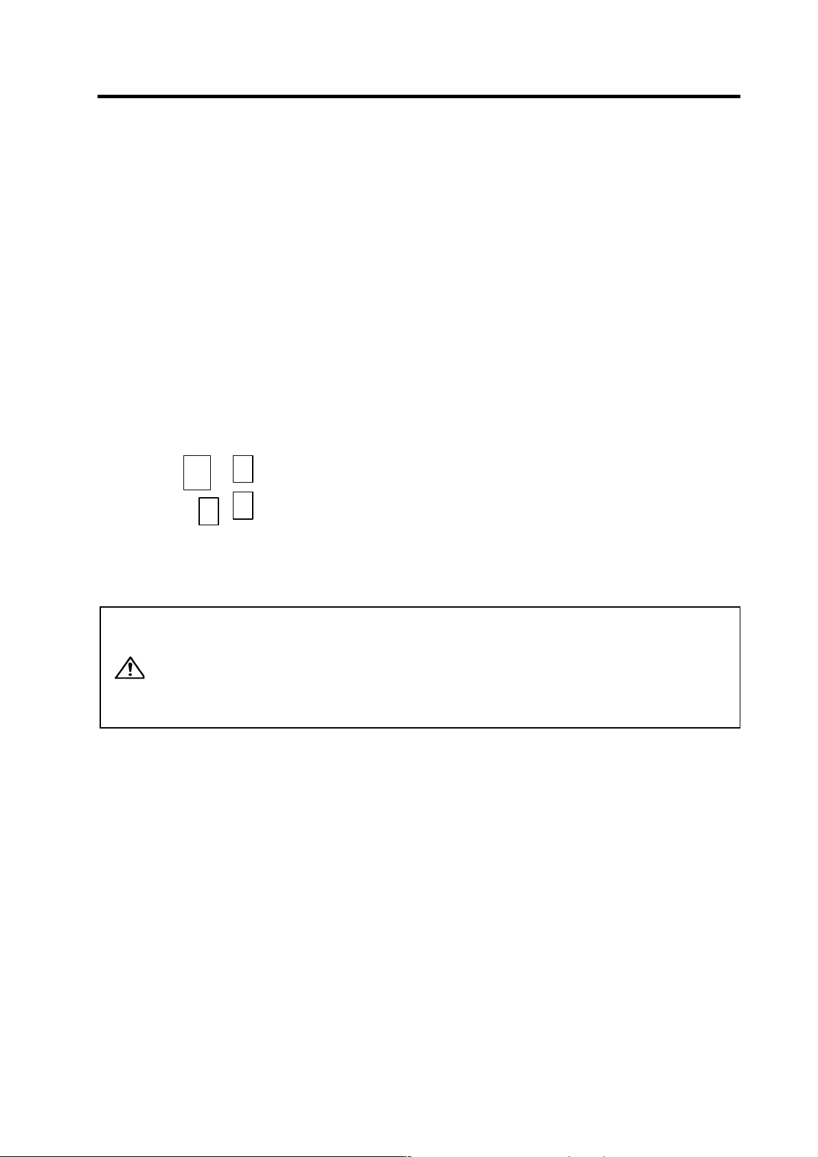
(1) Layout of display unit
Open the cover on the right side of the LED located in the upper part of the spindle drive unit. The
following switch and push-buttons are found there.
Rotary SW : Used to change the display mode.
UP button : Used to increase the data value.
DOWN button : Used to decrease the data value.
Rotary SW
UP
SET
DOWN
SET button : Used to start/finish changing the parameter setting value.
(2) Parameter setting method
CAUTION
1. Change the parameter in the state where the start signal is not input.
2. All the parameter Nos. have to be converted into HEX when input. The
targeted setting data, whether if it is DEC, must also be converted into
HEX. (If the setting value is HEX, set the value as it is.)
3. When the parameter is changed with this method, always turn the spindle
drive unit's power ON → OFF, or turn the alarm reset signal ON → OFF to
validate the parameter.
1) Turn the drive unit main power supply ON.
2) Set the rotary SW to "1".
At this time, main/sub is displayed on the left side of the spindle drive unit 7-segment LED, and
the upper one digit of the parameter No. is displayed on the other side.
[1] Set the upper digit of parameter No. with UP/DOWN buttons.
Set "0" for the parameter No. SP255 or lower, set "1" for the parameter No. SP256 or higher.
[2] Switch Main/Sub with SET button. Main and Sub switch every time the SET button is pressed.
When "1" is displayed on the left side of LED, "Main" is selected; when "2" is displayed, "Sub"
is selected. Set at the main side for all the specifications other than 1A2M.

3. Setup
3 - 5
3) Set the rotary SW to "2".
At this time, the spindle drive unit 7-segment LED indicates the lower two digits of parameter No.
Use the UP/DOWN buttons to set the lower two digits of the parameter No. Keep the button
pressed to expedite the operation.
(Setting example)
Parameter No.
LED setting
value
SP001 1
SP010 A
SP129 81
SP255 FF
SP320 40 (Note that, however, the rotary SW is "1" at this time and so
"1" must be set on the right side of LED.)
4) Set the rotary SW to "3".
At this time, the spindle drive unit 7-segment LED indicates the upper two digits of the
parameter setting value.
[1] The display lamp starts flashing rapidly when the SET button is pressed.
[2] Use the UP/DOWN button to change the setting value. Keep the button pressed to expedite
the operation.
[3] Press the SET button once again when reaching the target setting value. The flashing of the
display lamp slows down.
5) Set the rotary SW to "4".
At this time, the spindle drive unit 7-segment LED indicates the lower two digits of the parameter
setting value.
[1] The display lamp starts flashing rapidly when the SET button is pressed.
[2] Use the UP/DOWN button to change the setting value. Keep the button pressed to expedite
the operation.
[3] Press the SET button once again when reaching the target setting value. The flashing of the
display lamp slows down.
(Setting example)
Target setting value (DEC) Setting value - Rotary SW "3" Setting value - Rotary SW "4"
1
0 1
10 0 A
100 0 64
1000 3 E8
10000 27 10
32767 7F FF
This is the end of setting. Set the rotary SW back to "0" and turn the drive unit's power ON again or
enter the reset input.
3. Setup
3 - 6
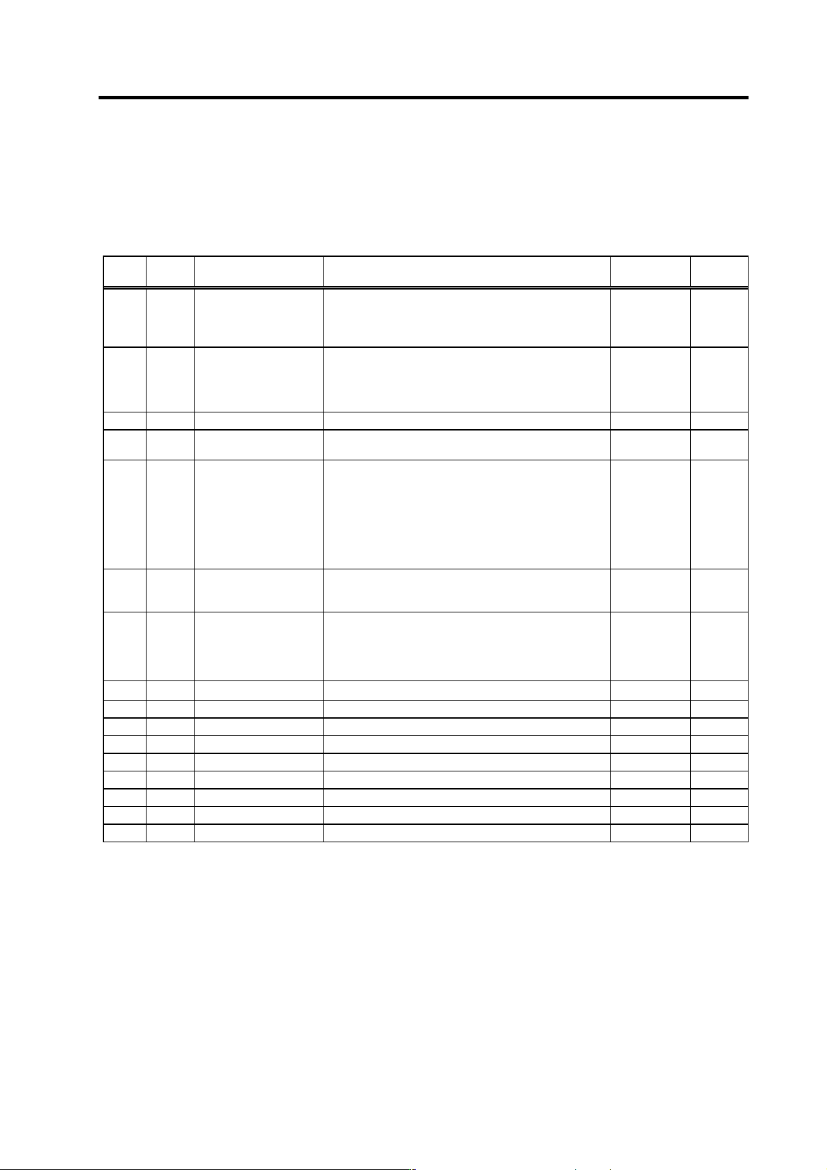
3-2-2 List of spindle parameters
These parameters are sent to the spindle drive unit when the NC power is turned ON. The standard
parameters are designated with the "Spindle parameter setting list" enclosed when the spindle motor is
delivered. There may be cases when the machine specifications are unclear, so the parameters
determined by the machine specifications should be confirmed by the user.
No. Abbr. Parameter name Details
Setting range
(Unit)
Standard
setting
SP001 PGM*
Magnetic sensor, motor
PLG orientation position
loop gain
The orientation time will be shorter when the value is
increased, and the servo rigidity will increase. On the
other hand, the vibration will increase, and the machine
will sway easily.
0 to 1000
(0.1 rad/s)
100
SP002 PGE*
Encoder orientation
position loop gain
The orientation time will be shorter when the value is
increased, and the servo rigidity will increase. On the
other hand, the vibration will increase, and the machine
will sway easily.
0 to 1000
(0.1 rad/s)
100
SP003 Not used. Set "0". 0 0
SP004 OINP*
Orientation in-position
width
Set the position error range in which an orientation
completion signal is output.
1 to 2880
(1/16°)
16
SP005 OSP
Orientation mode
speed clamp value
Set the motor speed limit value to be used when the
speed loop is changed to the position loop in orientation
mode.
When this parameter is set to "0", SP017 (TSP) becomes
the limit value.
In the spindle side speed clamp valid
(SP097:SPEC0-bit4=1), the speed limit value will be the
spindle speed instead of the motor speed.
0 to 32767
(r/min)
0
SP006 CSP*
Orientation mode
deceleration rate
As the set value is larger, the orientation time becomes
shorter. However, the machine becomes likely to
overshoot.
1 to 1000 20
SP007 OPST*
Position shift amount for
orientation
Set the stop position for orientation.
(1) Motor PLG and spindle side detector
Set a value obtained by dividing 360° by 4096.
(2) Magnetic sensor orientation
Divide -5°C to +5° by 1024, and set 0° as "0".
(1)
0 to 4095
(2)
-512 to 512
0
SP008
Not used. Set
"0".
0 0
SP009 Not used. Set "0". 0 0
SP010 Not used. Set "0". 0 0
SP011 Not used. Set "0". 0 0
SP012 Not used. Set "0". 0 0
SP013 Not used. Set "0". 0 0
SP014 Not used. Set "0". 0 0
SP015 Not used. Set "0". 0 0
SP016 Not used. Set "0". 0 0
Parameters having an abbreviation with "*" (PGM*, etc.) are validated right after the settings are changed by the personal computer,
without turning the spindle drive unit's power ON and OFF.