MDS-C1-SPA Series INSTRUCTION MANUALib1500152(eng)a.pdf - 第154页
4. Spindle Adjustment 4 - 63 [4] The stop position d oes not change even when the position shift parameter is changed. Cause Investigation i tem Remedy Remarks 1 Parameter setting values are incorrect The position shift …

4. Spindle Adjustment
4 - 62
(9) Troubleshooting
For the troubles during orientation, refer to (7) Troubleshooting in the section "4-3-3 Adjusting the
orientation control".
[1] Not executing indexing operation
Cause Investigation item Remedy Remarks
1 Parameter
setting values are
incorrect
Forward/reverse run indexing start is
not set to the general-purpose input.
Or, the input in which the actual
forward/reverse run indexing signal is
wired and the location set in the
parameter are different.
Set either "2" or "3" in one of the
general-purpose input parameters
SP129 to SP140 which corresponds to
the input section where the orientation
command has been wired.
When the forward/reverse run indexing
signal is ON, the orientation command
is OFF.
To run indexing operations, always
keep the orientation command signal
turned ON.
2 Sequence error
The external stop position data has not
been changed.
Officially change the external stop
position data.
3 Incorrect wiring The connector pin numbers are
incorrect. The inserted connector
number is incorrect.
The cable is disconnected.
Correct the wiring.
Replace the cable.
[2] The motor overtravels and stops (The motor sways when stopping.)
Cause Investigation item Remedy Remarks
The selected gear and the actual gear
are different.
Adjust gear selection inputs (GR1,
GR2) according to the actual gear.
The gear ratio parameters:
SP025(GRA1) to SP032(GRB4) are
incorrect.
Correctly set SP025(GRA1) to
SP032(GRB4).
Half the deceleration rate during
orientation parameter SP006 (CSP) to
solve the problem.
Readjust SP006(CSP). This also applies
to:
SP107(CSP2)
SP108(CSP3)
SP109(CSP4)
SP121(MPCSH)
SP122(MPCSL)
1 Parameter
setting values are
incorrect
Position loop gain parameter
Change the value of SP001(PGM),
SP002(PGE) to solve the problem.
Readjust SP001(PGM), SP002(PGE). This also applies
to:
SP119(MPGH)
SP120(MPGL)
[3] The stopping position deviates
Cause Investigation item Remedy Remarks
There is backlash or slipping between
the spindle and encoder.
The gear ratio between the spindle and
encoder is not 1:1 or 1:2.
For spindle side
detector
orientation
1 Mechanical
cause
The stopping position is not deviated
with the encoder axis.
There is backlash or slipping between
the spindle and motor.
The gear ratio between the spindle and
motor is not 1:1.
For motor PLG
orientation
The position detector's cable is
relayed with a terminal block
(connector), etc.
Do not relay the cable.
The position detector cable's shield is
not treated properly.
Properly treat the shield.
2 Noise
The peeled section of signal wire at
the position detector cable's connector
section is large. (A large section is not
covered by the shield.)
Keep the peeled section to 3cm or less
when possible. Keep the peeled section
as far away from the power cable as
possible.

4. Spindle Adjustment
4 - 63
[4] The stop position does not change even when the position shift parameter is changed.
Cause Investigation item Remedy Remarks
1 Parameter
setting values are
incorrect
The position shift was changed to 2048
when the gear ratio between the
spindle and encoder was 1:2 (one
encoder rotation at two spindle
rotations).
If the gear ratio on the left is established
between the spindle and encoder, the
position shift amount for one spindle
rotation is 2048 instead of 4096.
[5] The machine vibrates when stopping
Cause Investigation item Remedy Remarks
1 Parameter
setting values are
incorrect
The gear ratio parameters SP025
(GRA1) to SP032 (GRB4) are incorrect.
Correctly set SP025 (GRA1) to SP032
(GRB4).
The vibration frequency is several Hz. Decrease the position loop gain
parameters SP001 (PGM) and SP002
(PGE).
Increase the current loop gain for
orientation parameters SP105 (IQGO)
and SP106 (IDGO).
2 The orientation
adjustment is
faulty
The vibration frequency is 10Hz or
more.
Decrease the speed loop gain for
orientation parameters SP098 (VGOP)
and SP099 (VGOI).
Decrease the current loop gain for
orientation parameters SP105 (IQGO)
and SP106 (IDGO).
[6] The orientation complete signal, indexing complete signal is not output
Cause Investigation item Remedy Remarks
1 Parameter
setting values are
incorrect
Orientation completion or indexing
completion is not set to the
general-purpose output. Or the actual
orientation completion is wired to a
different output from the one set in the
parameter .
Set "1" or "2" in one of the
general-purpose output parameters
SP141 to SP154 which corresponds to
the output section where the orientation
completion has been wired.
The in-position parameter SP004
(OINP) is too small.
Review the in-position range, and
increase SP004 (OINP).
2 The machine's
load is heavy
Stop the delay compensation control
during orientation stop to solve the
problem. (Change to the PI control to
solve the problem.)
Review the values set for the speed
loop gain for orientation parameters
SP098 (VGOP), SP099 (VGOI) and
SP100 (VGOD).
3 Carry out the items for [1] Orientation does not take place (motor keeps rotating).
4. Spindle Adjustment
4 - 64
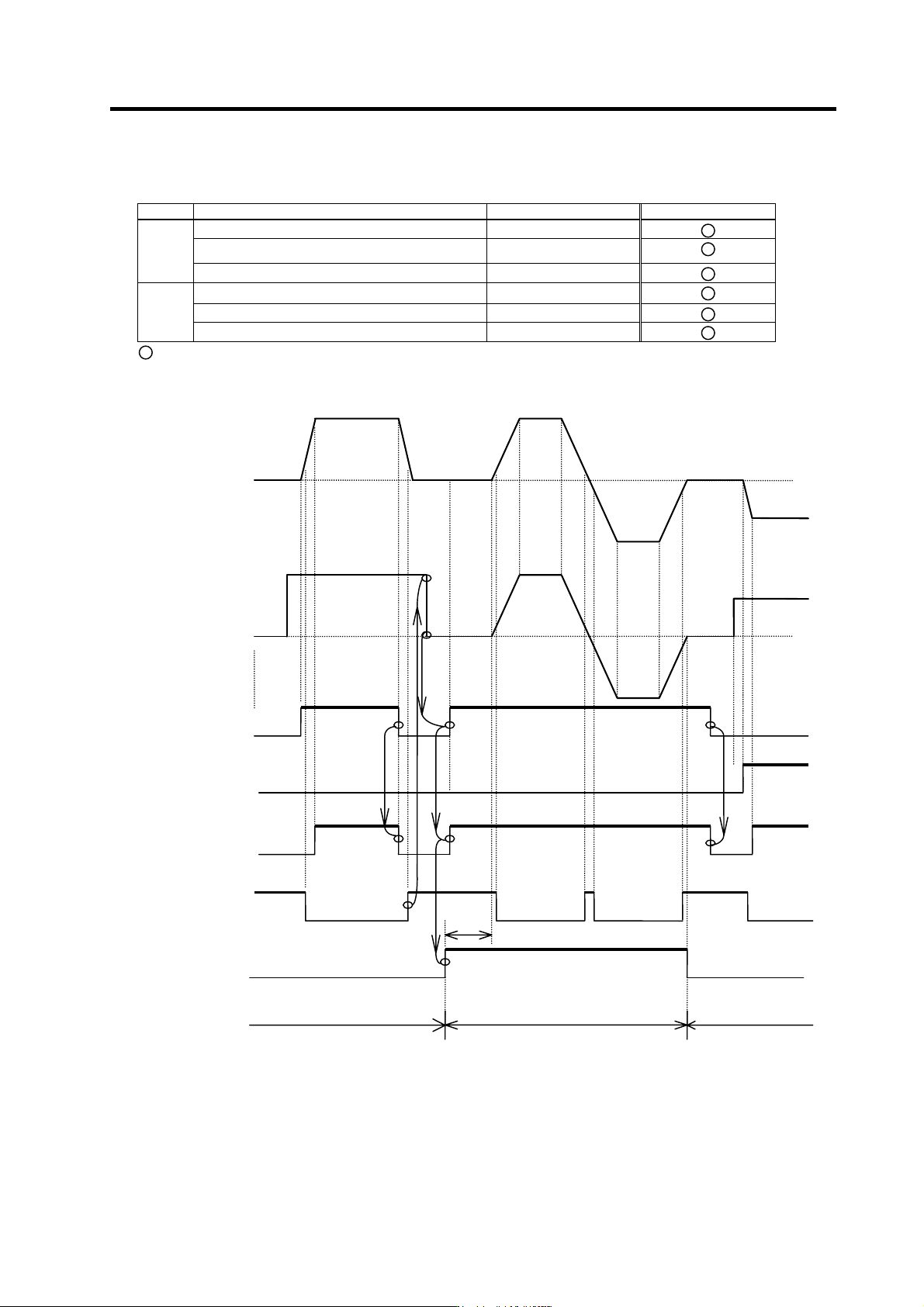
4-3-5 Adjusting S-analog high-speed tapping control
(1) Necessary input/output
I/O Signal name I/O mode Mandatory/Optional
S-analog high-speed tapping input (HSP) General-purpose input
Analog speed command input (bipolar) Analog input
Input
Forward run signal (SRN), reverse run signal (SRI) Special input
Pulse feedback output signal Special output
Up-to-speed output signal General-purpose output
Output
Zero speed output signal General-purpose output
: Mandatory
(2) Operation sequence
OFF
ON
OFF
t1
Motor speed
Forward run start
Up-to-speed
S-analog high-speed
tapping
OFF OFF
ON ON
ON
ON
ON
ON ON ON
ON
OFF
OFF
OFF
OFF
OFF
OFF
OFF
OFF
ON
O
O
S-analog speed
command voltage
Reverse run start
Zero speed
Mode
Regular speed loop Regular speed loop S-analog synchronous tapping mode