MDS-C1-SPA Series INSTRUCTION MANUALib1500152(eng)a.pdf - 第134页
4. Spindle Adjustment 4 - 43 Default parameter settings for detector in use No. Abbr . Parameter name (a) Motor PLG (b) Spindle detector (c) Magnetic sensor SP123 MGD0* Magnetic sensor output peak value - - S tandard: 54…

4. Spindle Adjustment
4 - 42
The default orientation control parameters for each detector are as shown below. Confirm that these
parameters are correctly set according to the machi ne specifications.
Default parameter settings for detector in use
No. Abbr. Parameter name
(a) Motor PLG (b) Encoder
(c) Magnetic
sensor
SP001 PGM*
Magnetic sensor and motor PLG orientation position
loop gain
100 - 100
SP002 PGE* Encoder orientation position loop gain - 100 -
SP004 OINP* Orientation in-position width 14 14 16
SP005 OSP Orientation mode speed clamp value 0 0 0
SP006 CSP* Orientation mode deceleration rate 20 20 20
SP007 OPST* In-position shift amount for orientation 0 0 0
SP025 GRA1 Spindle gear teeth count 1 1 * *
SP026 GRA2 Spindle gear teeth count 2 1 * *
SP027 GRA3 Spindle gear teeth count 3 1 * *
SP028 GRA4 Spindle gear teeth count 4 1 * *
SP029 GRB1 Motor shaft gear teeth count 1 1 * *
SP030 GRB2 Motor shaft gear teeth count 2 1 * *
SP031 GRB3 Motor shaft gear teeth count 3 1 * *
SP032 GRB4 Motor shaft gear teeth count 4 1 * *
SP037 SFNC5 Spindle function 5 0004 0001 0002
SP096 EGAR Encoder gear ratio - * -
SP097 SPECO Orientation specification 0000 0000 0000
SP098 VGOP
Speed loop gain proportional term in orientation
mode
63 63 63
SP099 VGOI Speed loop gain integral term in orientation mode 60 60 60
SP100 VGOD
Speed loop gain delay advance term in orientation
mode
15 15 15
SP101 DINP Orientation advance in-position width 16 16 16
SP102 OODR Excessive error value in orientation mode 32767 32767 32767
SP103 FTM Index positioning completion OFF time timer 200 200 200
SP104 TLOR Torque limit value after orientation completed 100 100 100
SP105 IQGO Current loop gain magnification 1 in orientation mode 100 100 100
SP106 IDGO Current loop gain magnification 2 in orientation mode 100 100 100
SP107 CSP2* Deceleration rate 2 in orientation mode 0 0 0
SP108 CSP3* Deceleration rate 3 in orientation mode 0 0 0
SP109 CSP4* Deceleration rate 4 in orientation mode 0 0 0
SP114 OPER* Orientation pulse miss check value 0 0 0
SP115 OSP2* Orientation control speed clamp value 2 0 0 0
SP116 OPYVR*
Minimum excitation value after changeover
(2nd minimum excitation rate)
0 0 0
SP117 ORUT* Fixed control constant 0 0 0
SP118 ORCT* Orientation control number of retry times 0 0 0
SP119 MPGH*
Orientation control position loop gain H coil
magnification
0 0 0
SP120 MPGL*
Orientation control position loop gain L coil
magnification
0 0 0
SP121 MPCSH* Orientation deceleration rate H coil magnification 0 0 0
SP122 MPCSL* Orientation deceleration rate L coil magnification 0 0 0
(Note 1) *: Set according to machine specifications, -: Setting irrelevant
(Note 2) For parameters with an asterisk * in the abbreviation, such as PGM*, if the settings of the parameters have been
changed with a personal computer, the parameters are validated without turning the spindle drive unit's power ON/OFF
immediately after the settings have been changed.

4. Spindle Adjustment
4 - 43
Default parameter settings for detector in use
No. Abbr. Parameter name
(a) Motor PLG (b) Spindle detector
(c) Magnetic
sensor
SP123 MGD0* Magnetic sensor output peak value - -
Standard: 542
Small type: 500
SP124 MGD1* Magnetic sensor linear zone width - -
Standard: 768
Small type: 440
SP125 MGD2* Magnetic sensor changeover point - -
Standard: 384
Small type: 220
SP129
to
SP140
HI01
to
HI12
General-purpose input selection1 to 12
1: Orientation
start
7: Gear
selection 1
8: Gear
selection 2
1: Orientation start
7:Gear selection 1
8: Gear selection 2
1: Orientation
start
7: Gear
selection 1
8: Gear
selection 2
SP141
to
SP154
HO1e
to
HO6c
General-purpose output selection
open emitter1 to open corrector6
1: Orientation
complete
1: Orientation
complete
1: Orientation
complete
SP225 OXKPH*
Position loop gain magnification after orientation
completed (H coil)
0 0 0
SP226 OXKPL*
Position loop gain magnification after orientation
completed (L coil)
0 0 0
SP227 OXVKP*
Speed loop prop ortional gain magnification after
orientation completed
0 0 0
SP228 OXVKI*
Speed loop cumulative gain magnification after
orientation completed
0 0 0
(Note 1) *: Set according to machine specifications, -: Setting irrelevant
(Note 2) Parameters having an abbreviation with "*" (MGD0*, etc.) are validated right after the settings are changed by the
personal computer, without turning the spindle drive unit's power ON and OFF.
4. Spindle Adjustment
4 - 44
(4) Adjusting the orientation deceleration control
[1] Polarity setting of sensor
Input the orientation command (ORC) when the machine is in the normal state. Confirm that the
operation stops at one point and the orientation complete signal (ORCF) turns ON even when
the operation is unstable. If the excessive error al arm (alarm 52) occurs, o r if the operation does
not stop and repeats forward/reverse run at a low-speed when using the magnetic sensor
orientation specifications, change the value for SP097/bit5 or bit6. If the excessive error alarm
occurs even after changing this value, carry out step [3].
No. Abbr. Parameter name Details
FEDCBA98765 4 3 2 10
ostp orze ksft gchg ips2 zdir vg8x mdir fdir Oscl pyfx dmin odi2 odi1
bit Meaning when set to 0 Meaning when set to 1 Standard
5 fdir Encoder installation polarity: + Encoder installation polarity: – 0
6 mdir Magnetic sens or polarity: + Magnetic sensor polarity: – 0
SP097 SPECO* Orientation
specification
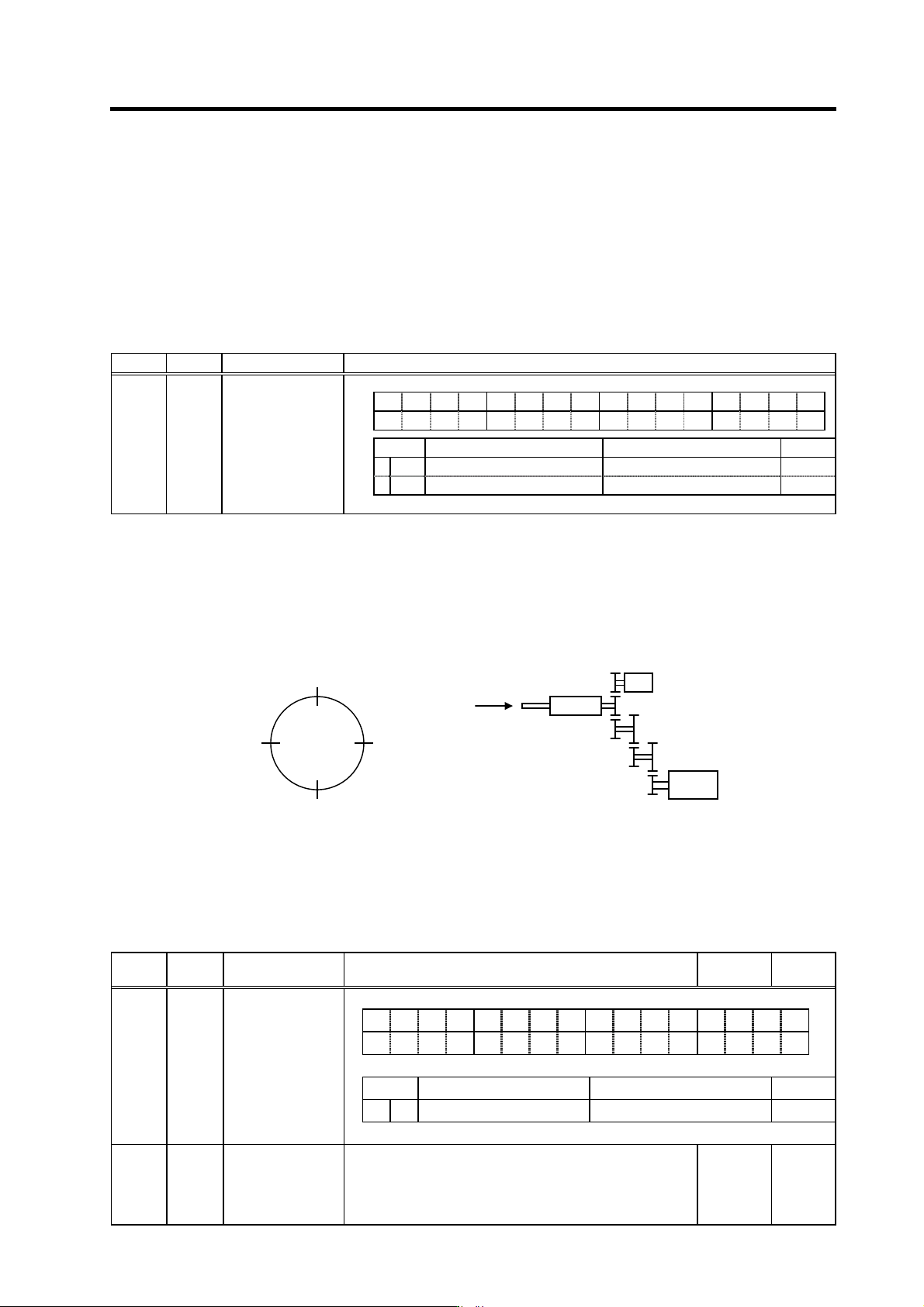
[2] Adjustment of orientation stop position
Next, adjust the in-position shift amount for orientation control: SP007 (OPST) so that the axis
stops at the target stop point. If the stop position command data is input from the spindle side
detector, or from an external source during motor PLG orientation, the operation will stop
according to the given data as shown in the drawing below regardless of the detector's
mounting direction. The 0° position sh own below is the position shifted by SP007 (OPST).
Orientation stop position
(Note) When "1" is set in SP037(SFNC5)/bit7, the stop position by the external stop position data can be changed
by 180° in the figure above. (0h: 0°, C00h: 90°, 800h: 180°, 400h: 270°)
No. Abbr. Parameter name Details
Setting
range
Standard
F E D C B A 9 8 7 6 5 4 3 2 1 0
dplg ospcl noplg nsno nosg psdir plgo mago enco
bit
Meaning when set to 0 Meaning when set to 1 Standard
7 psdir
Position shift (standard) Position shift (reverse direction)
0
SP037 SFNC5 Spindle function 5
SP007 OPST In-position shift
amount for
orientation
Set the stop position for orientation.
(1) Motor PLG, spindle side detector:
Set the value by dividing 360° by 4096.
(2) Magnetic sensor:
Divide –5° to +5° by 1024 and put 0° for 0.
(1) 0 to 4095
(2) -512 to
512
0
View S
0h
(0°)
400h
(90°)
800h
(180°)
C00h
(270°)
S
p
indle side detecto
r
XS
p
indle
Spindle motor
A
BC
DE
F
S