MDS-C1-SPA Series INSTRUCTION MANUALib1500152(eng)a.pdf - 第115页
4. Spindle Adjustment 4 - 24 bit7. Index positioning completed (WRCF) This signal turns ON durin g indexing operation w hen the spindle position reaches the in-position range in respect to the target stop position. Once …
4. Spindle Adjustment
4 - 23
bit4. Orientation complete (ORCA)
This signal turns ON when the orientation command is input, and the spindle position is reached
the set range (within the in-position range) in respect to the target stop position. This signal turns
OFF when orientation is completed and the spindle position deviates from the in-position range,
but it will turn ON again when the spindle position enters the in-position range again. If the
orientation command is turned OFF, this signal will turn OFF even if the spindle position is within
the in-position range. The in-position range can be set with parameter SP004 (OINP).
Related spindle parameter
No. Abbr. Parameter name Details
Setting
range
Standard
SP004 OINP Orientation
in-position width
Set the position error range in which an orientation
completion signal is output.
1 to 2880
(1/16deg)
16
SP141
to
SP154
HO1e
to
HO6c
General-purpose
output selection
Open emitter 1 to
General-purpose
output selection
Open collector 6
Set the following value in any one of these parameters when
using the orientation complete output.
“1”: Orientation complete (ORCA)
0 to 23 0
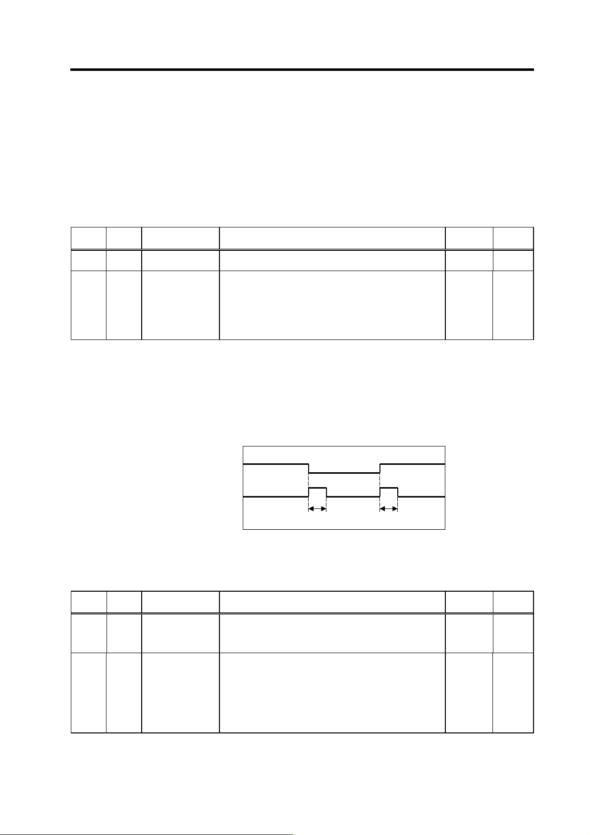
bit6. Changing coil (MKC)
When using the coil changeover motor, this signal turns ON for the time set in parameter SP059
(MKT) when the L coil selection command is turned ON or OFF. The coil is not changed when the
orientation command is input, so this signal will not turn ON even if the L coil selection signal is
turned ON or OFF. During orientation control, this signal will turn ON when the orientation
command turns OFF and the coil changeover operation takes place. Do not turn the start signal
ON or OFF while this signal is ON.
Changing coil (MKC) sequence
Related spindle parameter
No. Abbr. Parameter name Details
Setting
range
Standard
SP059 MKT* Winding changeover
base shut-off timer
Set the base shut-off time for contactor switching at coil
changeover.
Note that the contactor may be damaged with burning if the
value of this parameter is too small.
50 to 10000
(ms)
150
SP141
to
SP154
HO1e
to
HO6c
General-purpose
output selection
Open emitter 1
to
General-purpose
output selection
Open collector 6
Set the following value in any one of these parameters when
using the changing coil output.
“16”: Changing coil (MKC)
0 to 23 0
Changing coil (MKC)
ON
OFF
L coil selection command
(LCS)
ON
OFF
SP059SP059

4. Spindle Adjustment
4 - 24
bit7. Index positioning completed (WRCF)
This signal turns ON during indexing operation when the spindle position reaches the in-position
range in respect to the target stop position. Once this signal turns ON it will remain ON regardless
of the spindle position until the orientation signal turns OFF or the next indexing operation signal is
input.
This signal will turn OFF for the time set with paramet er SP103 (FTM ) when the indexing o peration
signal is input even if the current stop point and the next indexing position are in the in-position
range.
For the details, refer to the adjustment for the indexing control in the adjustment procedure for
each control.
Related spindle parameter
No. Abbr. Parameter name Details
Setting
range
Standard
SP103 FTM* Index positioning
completion OFF time
timer
Set the time for forcedly turn OFF the index positioning
completion signal (different from the orientation completion
signal) after the leading edge of the indexing start signal.
0 to 10000
(ms)
200
SP141
to
SP154
HO1e
to
HO6c
General-purpose
output selection
Open emitter 1 to
General-purpose
output selection
Open collector 6
Set the following value in any one of these parameters when
using the index positioning completed output.
“2”: Index positioning completed (WRCF)
0 to 23 0
bit8. In 1-drive unit 2-motor changeover (MTC)
This signal turns ON during motor changeover with 1-drive unit 2-motor specification.
No. Abbr. Parameter name Details
Setting
range
Standard
SP141
to
SP154
HO1e
to
HO6c
General-purpose
output selection
Open emitter 1 to
General-purpose
output selection
Open collector 6
Set the following value in any one of these parameters when
using the in changeover (for 1-drive unit 2-motor changeover)
output.
“17”: In changeover
(for 1-drive unit 2-motor changeover) (MTC)
0 to 23 0

4. Spindle Adjustment
4 - 25
bitA. Torque reach (TLU)
This signal turns ON when the start command is input and the torque command in the drive unit
reaches to the clamp value.
Related spindle parameters
No. Abbr. Parameter name Details
Setting
range
Standard
SP141
to
SP154
HO1e
to
HO6c
General-purpose
output selection
Open emitter 1
to
General-purpose
output selection
Open collector 6
Set the following value in any one of these parameters when
using the torque reach output.
“3”: Torque reach (TLU)
0 to 23 0
bitB. In emergency stop (EMGA)
This signal turns ON when the emergency stop input is turned ON.
Related spindle parameters
No. Abbr. Parameter name Details
Setting
range
Standard
SP141
to
SP154
HO1e
to
HO6c
General-purpose
output selection
Open emitter 1
to
General-purpose
output selection
Open collector 6
Set the following value in any one of these parameters when
using t the in emergency stop output.
“10”: In emergency stop (EMGA)
0 to 23 0