MDS-C1-SPA Series INSTRUCTION MANUALib1500152(eng)a.pdf - 第90页
3. Setup 3 - 30 (7) Checking the Z phase and A phase difference Check the output signal waveform by measuring the signals of the che ck terminals on the PCB with the DC range of the synchroscope. A phase output signal ..…
3. Setup
3 - 29
(5) Confirming the Z phase pulse width
Check the output signal waveform by measuring the signals of the check terminals on the PCB
with the DC range of the synchroscope.
A phase output signal...... Across A-G
Z phase output signal...... Across Z-G
The output signal waveform is confirmed during motor forward run and reverse run. Set the
synchroscope as follows to measure the waveform during each run direction.
During forward run .......... Apply a trigger at the rising edge of the Z phase output signal
During reverse run .......... Apply a trigger at the falling edge of the Z phase output signal
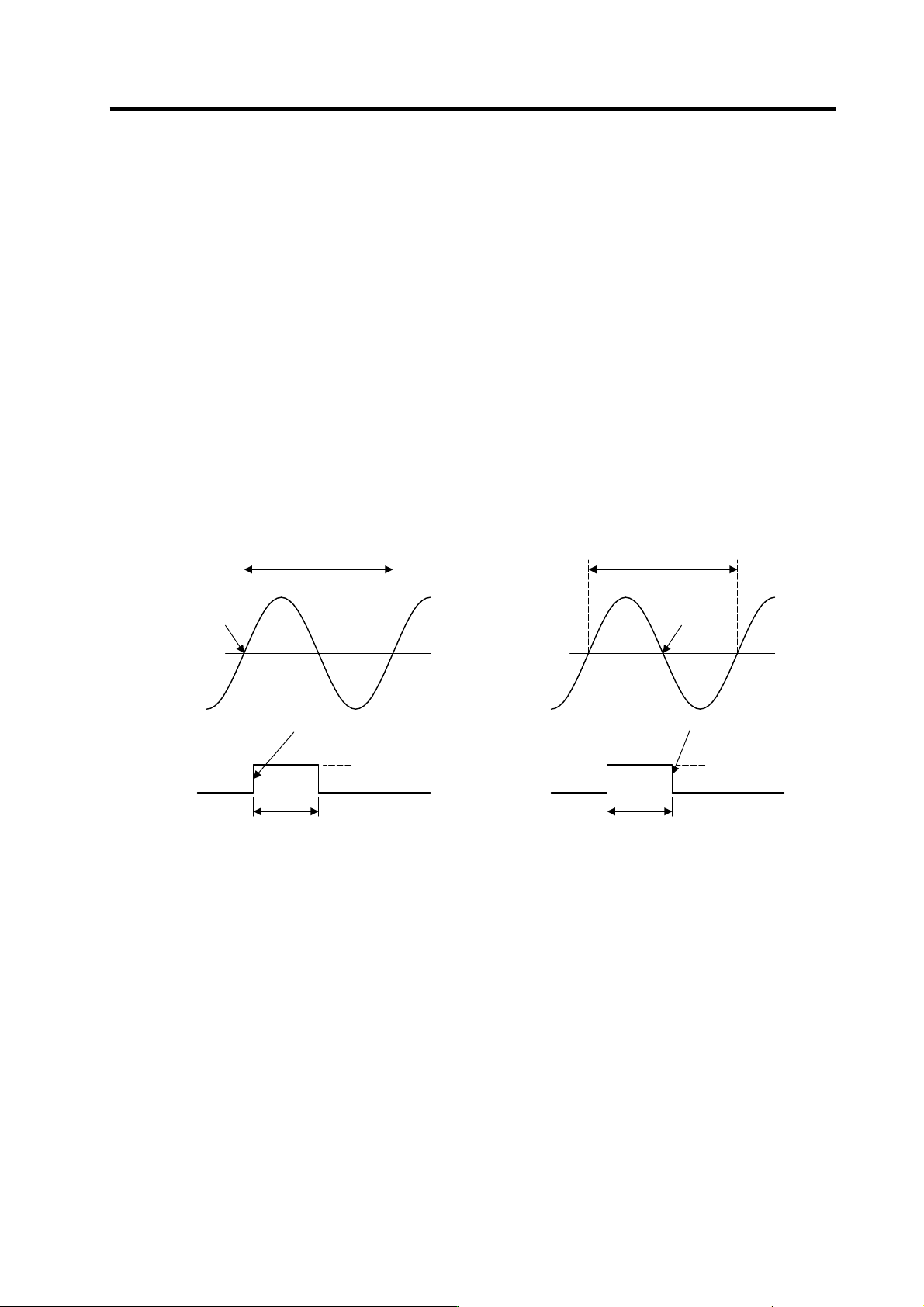
Confirm that the Z phase pulse width (time that the Z phase signal is at the "H" level = approx. 15V)
is 40% or more and 60% or less, when one cycle of the A phase signal is calculated as 100%. The
normal Z phase output signal waveform when run at the reference speed is shown below. If the
output signal waveform is not as shown below, refer to the next section "(6) Adjusting the Z phase
pulse width" and adjust.
The Z phase pulse width has been adjusted at shipment, with a combination of the sensor section
and PCB section having the same serial No. Thus, it normally does not need to be adjusted. If a
sensor section and PCB section having different serial numbers must be used, causing the Z
phase pulse width to deviate from the specified range, carry out the adjustment.
A phase/Z phas e output signal waveform
during forward run
A pha se/Z phas e output signal waveform
during reverse run
(6) Adjusting the Z phase pulse width
The Z phase pulse width can be adjusted with potentiometer VR5 on the PCB. VR5 is fixed after it
has been tested and adjusted to match the sensor section and PCB section having the same serial
No., so do not turn it unless a sensor section and PCB section with different serial numbers must
be used.
A phase
0V
One A
p
hase c
y
cle = 100%
R
p
oint
Z phase pulse width: 40 to 60%
A
pply a trigger at the falling
edge of the Z phase
H level (reference
volta
g
e +15V
)
L level
Z phase
A phase
0V
One A
p
hase c
y
cle = 100%
Q
p
oint
A
pply a trigger at the rising
edge of the Z phase
H level (reference
volta
g
e +15V
)
L level
Z
p
hase
Z phase pulse width: 40 to 60%
3. Setup
3 - 30
(7) Checking the Z phase and A phase difference
Check the output signal waveform by measuring the signals of the check terminals on the PCB
with the DC range of the synchroscope.
A phase output signal...... Across A-G
Z phase output signal...... Across Z-G
The output signal waveform is confirmed during motor forward run and reverse run. Set the
synchroscope as follows to measure the waveform during each run direction.
During forward run ..... Apply a trigger at the rising edge of the Z phase output signal
During reverse run ..... Apply a trigger at the falling edge of the Z phase output signal
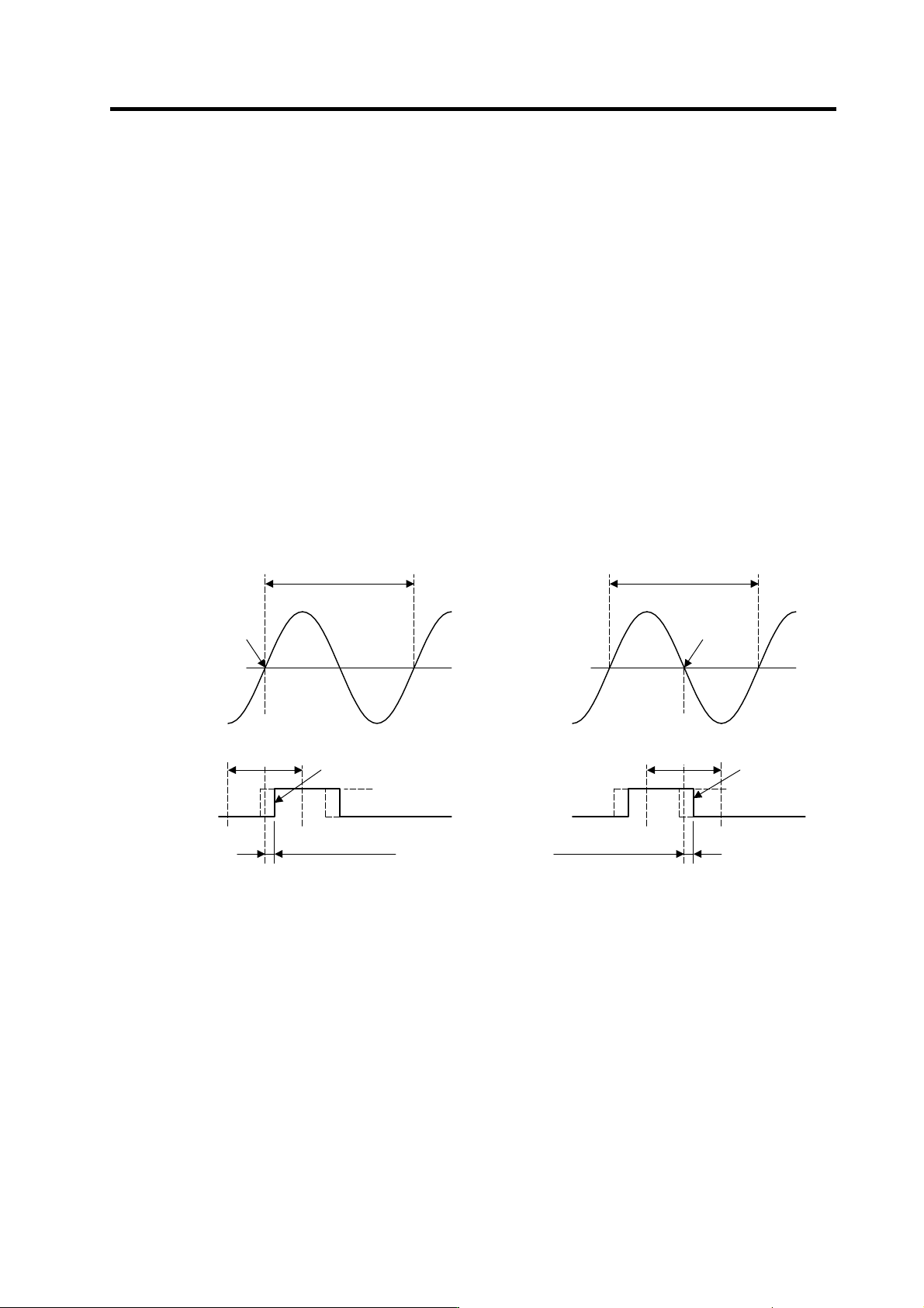
The phase difference for the Z phase signal and A phase signal is defined as follows.
During forward run ..... Time difference between Z phase output signal rising edge and A
phase output signal zero point (Q point)
During reverse run ..... Time difference between Z phase output signal falling edge and A
phase output signal's 1/2 cycle point (R point)
Confirm that the phase difference between the Z phase to the A phase is within ±25% during both
forward and reverse run when one cycle of the A phase signal is calculated as100%. If the output
signal waveform is not as shown below, refer to the next section "(8) Adjusting the Z phase and A
phase difference" and adjust.
Confirming the Z phase signal phase difference
during forward run
Confirming the Z phase signal phase difference
during reverse run
One A
p
hase c
y
cle = 100%
One A
p
hase c
y
cle = 100%
Phase difference of
A
phase and Z phase
Tolerable
range of phase
difference
±
25%
Phase difference of A phase and Z phase
Tolerable
range of phase
difference
±
25%
A phase
0V
R
p
oint
A
pply a trigger at the falling
edge of the Z phase
H level (reference
volta
g
e +15V
)
L level
Z phase
A phase
0V
Q
p
oint
A
pply a trigger at the rising
edge of the Z phase
H level (reference
volta
g
e +15V
)
L level
Z
p
hase
3. Setup
3 - 31
(8) Adjusting the Z phase and A phase difference
[1] Stop the motor, and make sure that the detection gears are not rotating. The sensor could be
damaged if adjustments are carried out while the gears are rotating.
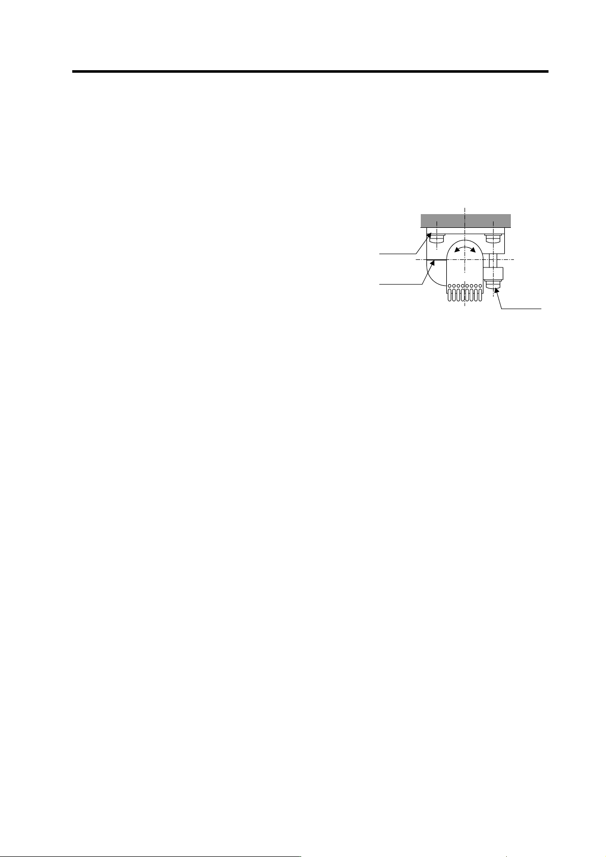
[2] Using a clearance gauge, adjust so that the gap between the sensor direction surface and the
detection gears’ circumference is 0.15±0.01mm, and loosen the sensor fixing screw.
[3] The phase difference of the Z phase to the A phase can be adjusted by rotating the sensor as
shown on the right. At this time, rotate the sensor a little bit while using the marking lines on
the sensor and installation seat as a guide.
[4] Tighten the sensor fixing screw so that the sensor
does not move, and confirm that the gap between the
sensor detection surface and detection gears'
circumference is 0.15 ± 0.01mm. Then, rotate the
gears and confirm the phase difference as explained
above.
[5] When the phase difference is within the tolerable
range, apply a locking agent on the sensor fixing
screw, and then fix the sensor. Check the gap again
after fixing the sensor.
Marking
line
Rotate
Sensor
fixing
screw
Sensor
installation
seat
2.1.1.1.1Adjustin