MDS-C1-SPA Series INSTRUCTION MANUALib1500152(eng)a.pdf - 第49页
2. Wiring and Connection 2 - 21 2-5-3 Main circuit control (1) Contactor ON sequence Main circuit power is turned ON in the sequenc e shown below when an emergency stop status is canceled. OFF ON Machine re ady comple te…
2. Wiring and Connection
2 - 20
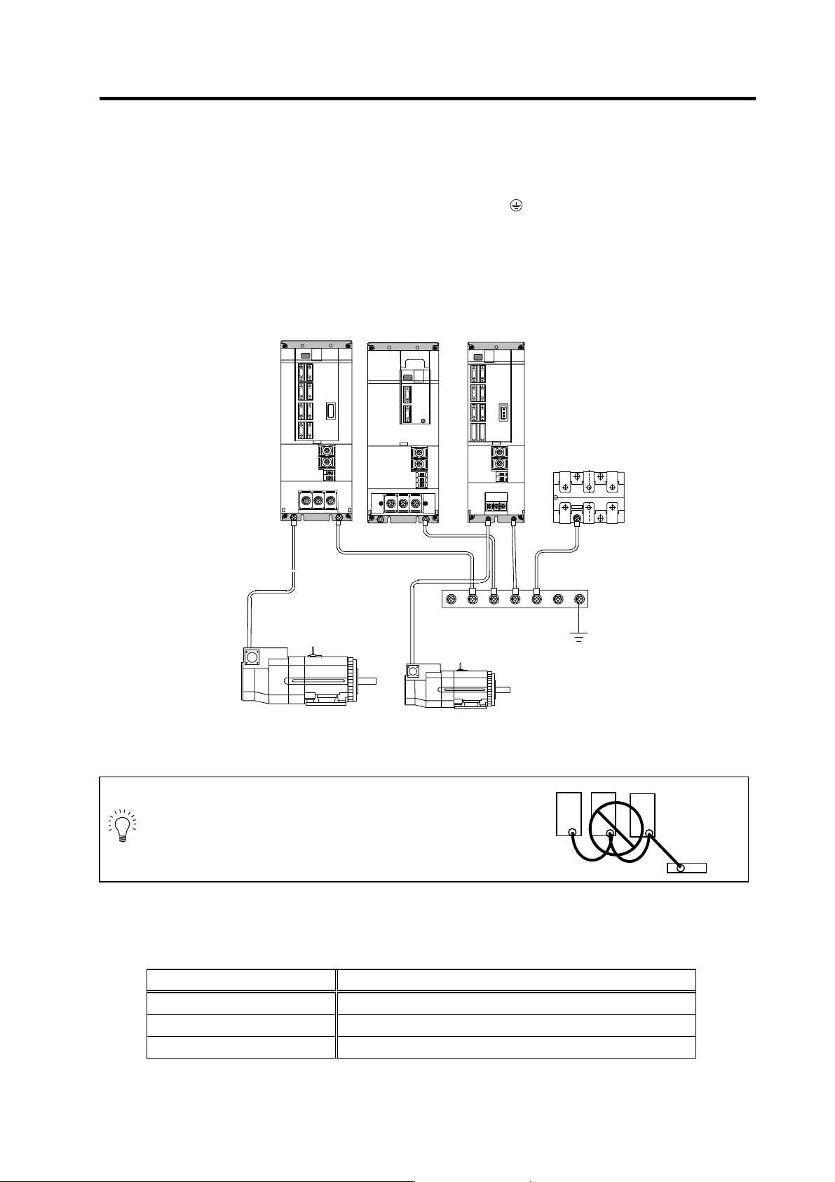
2-5-2 Connecting the grounding cable
(1) Connecting the protective grounding (PE) and frame ground (FG)
Each unit has a terminal or mounting hole to connect PE (
) or FG.
Please connect an earth wire to the main ground of a cabinet or a machine frame at one point.
Ground each device according to the grounding conditions set forth by each country. (Typically, a
Y-connection neutral point ground is used in Europe.)
PE: Grounding to provide protection from electric shock, etc.
FG: Grounding to stabilize the operation of the devices, etc. (Suppress noise)
MDS-C1-SPA(No.1)
MDS-C1-CV
B-AL
SJ Series motor
Grounding plate
MDS-C1-SPA(No.2)
POINT
Do not connect the grounding cable from
each unit directly to the grounding plate.
Noise from other units could result in
malfunctions.
(2) Grounding cable size
Earth wire size should follow the following table.
Type Grounding cable size (Required grounding)
MDS-C1-CV Unit Larger than thickness of wire connected to TE1 (L1/L2/L3). (PE)
MDS-C1-SPA[] Unit Larger than thickness of wire connected to TE1 (U/V/W). (PE)
B-AL (AC Reactor) 5.5 mm
2
(AWG10) or more (FG)
Unit
Grounding
plate
Unit
Grounding
plate
2. Wiring and Connection
2 - 21
2-5-3 Main circuit control
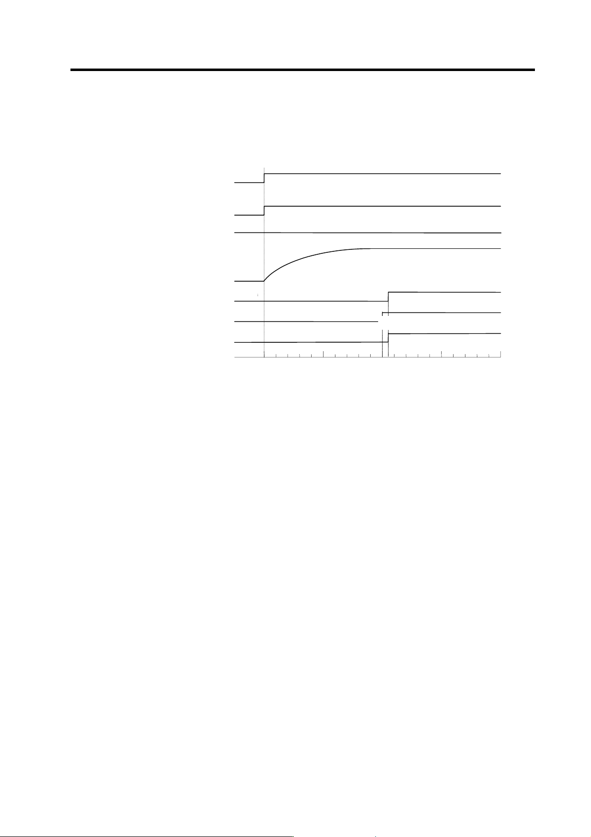
(1) Contactor ON sequence
Main circuit power is turned ON in the sequence shown below when an emergency stop status is
canceled.
OFF
ON
Machine ready complete input
signal (READY)
Emergency stop (EMG)
OFF
ON
Contactor co ntrol ou tp ut (MC1)
ON
OFF
Motor ON (GATE)
ON
OFF
ON
OFF
In read y ON signal (ron)
ON
OFF
Forward run/reverse run signal
(SRN, SRI)
0
500 1000 1500
Time (ms)
Command input enable
Ready completion
・
Contactor ON sequence
PN bus voltage
PN charging completed
2. Wiring and Connection
2 - 22
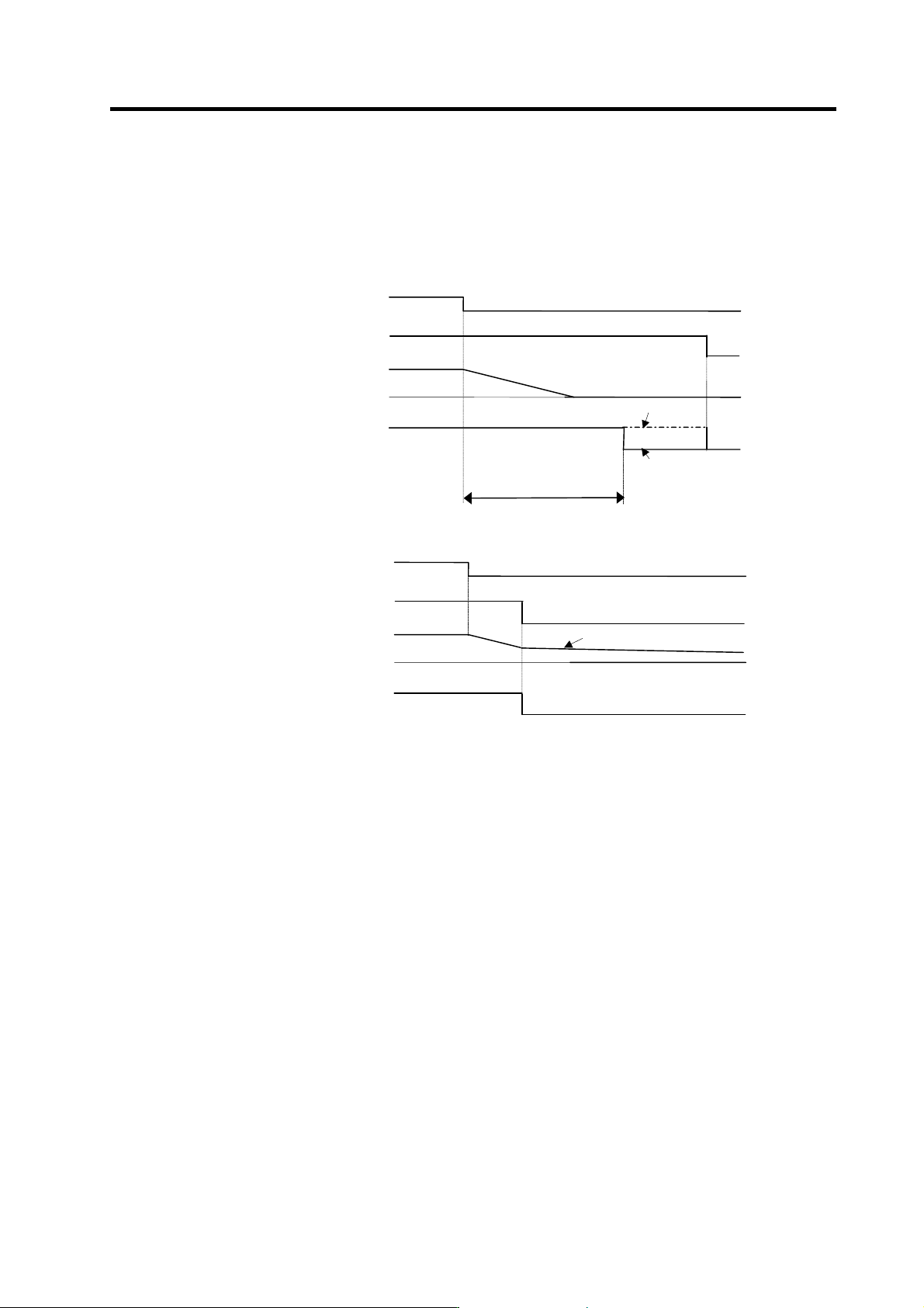
(2) Contactor shutoff sequence
During the emergency stop signal input (EMG), if the setting of SP193 is "0" or "1" after the spindle
motor decelerates to stop, the contactor is turned OFF after a certain amount of time. Even in the
emergency stop, the contactor is turned OFF immediately after the machine ready complete signal
(RDY) is turned OFF.
Machine ready complete input
signal (RDY)
Contactor control output (MC1)
ON
OFF
Contactor OFF sequence (When machine ready complete input signal is input after the setting time of SP055)
SP193: 2,3
OFF
ON
Emergency sto p (EMG)
Spindle motor
(deceleration stop)
0
Speed
OFF
ON
SP193: 0,1
Same as setting value of
SP055
Machine read y complete inpu t
(RDY)
Contactor control output (MC1)
ON
OFF
Contactor OFF sequence (When machine ready complete input signal is input during deceleration stop)
OFF
ON
Emergency stop (EMG)
Spindle motor
0
Speed
OFF
ON
Same as setting value of SP055
Motor coasts to stop.