MDS-C1-SPA Series INSTRUCTION MANUALib1500152(eng)a.pdf - 第163页
4. Spindle Adjustment 4 - 72 1) Stopping the spindle motor and changing the coil With this method, the high-speed coil and low-speed coils are viewed as ele ctronic gears that are handled in the same manner as th e mecha…
4. Spindle Adjustment
4 - 71
(3) Changing the coil in the speed control mode
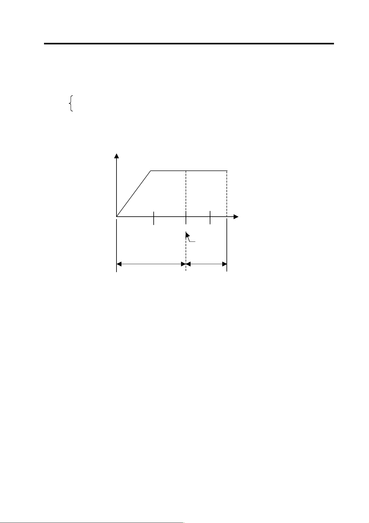
When the motor's output characteristics listed on the Mitsubishi motor rating table are as follows,
N2 is the coil changeover speed, and the following expression is established.
0≤N≤N2 is the low-speed coil usage range
N2<N is the high-speed coi l usage range
The method for inputting the L coil selection signal (LCS) to change from the low-speed coil range
N1 to the high-speed coil range speed N3 (vice versa) is explained in this section.
N1
N2 N3
Changeover
speed
High-speed coi l rangeLow-speed coil range
Speed N
Output
0
4. Spindle Adjustment
4 - 72
1) Stopping the spindle motor and changing the coil
With this method, the high-speed coil and low-speed coils are viewed as electronic gears that are
handled in the same manner as the mechanical gears.
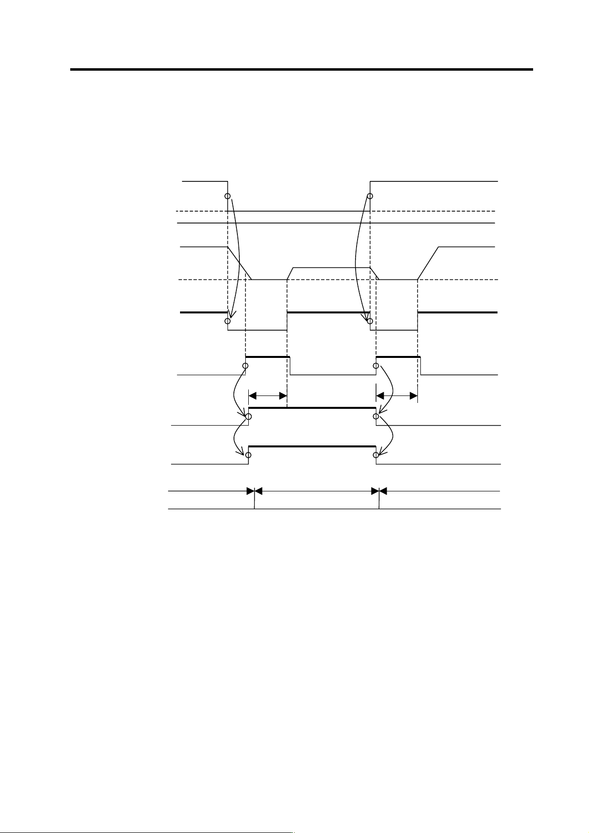
<Example of N3 → N1 → N3 changeover sequence>
N3
N1
0
N3
0
Speed command
Motor rotation speed command
Start signal
(SRN or SRI)
Zero speed output signal
(ZS)
L coil selection command
signal (LCS)
L coil selected signal
(LCSA)
N1
ON
ON
ON
OFF
OFF
ON
ON
OFF OFF OFF
ON
ON
OFF OFF
(Note) (Note)
OFF
OFF
High-speed coil selection Low-speed coil selection High-speed coil selection
[1] If the speed command changes to N1 while the motor is rotating in N3 (hig h-speed coil range),
the motor is stopped once by the user's seq uence. After confirmin g that the zero speed outp ut
signal (ZS) has turned ON, the L coil selection command signal (LCS) is turned ON. After
changing from the low-speed coil to the high-speed coil, the start signal (SRN or SRI) is turned
ON again, and the motor is accelerated to N1.
[2] In the same manner, when changi ng the sp eed co mmand from N1 to N3, the motor is stop ped
once. After confirming that the zero speed output signal (ZS) has turned ON, the L coil
selection command signal is turned OFF. After changing from the high-speed coil to the
low-speed coil, the start signal is turned ON, and the motor is rotated at the spe ed of N3.
(Note) Provide a time longer than T
M
from when the L coil selection command signal (LCS) is input to
when the start signal turns ON. Or, set the sequence so that the start signal turns ON after the coil
changed signal (MKC) changes from ON to OFF instead of using a timer.
4. Spindle Adjustment
4 - 73
2) Changing the coil during spindle motor rotation
This method uses the characteristics of coil changeover to change the coil during motor rotation,
and changing directly from the low-speed coil to the high-speed coil. The transition time is shorter
compared to the method explained in the previous section. The speed detection signal (SD) is
used with this method, and the L coil selection command signal (LCS) is input in the following
manner.
[1] To accelerate from a stopped state (To accelerate after zero speed output signal turns ON)
(i) First, judge the high-speed/low-speed coil range with the speed command, and select the
coil. (Input the L coil selection command signal (LCS).)
(ii) Next, turn the start signal ON and accelerate the motor.
(iii) Hold the L coil selection command signal (L CS) in the state of (i).
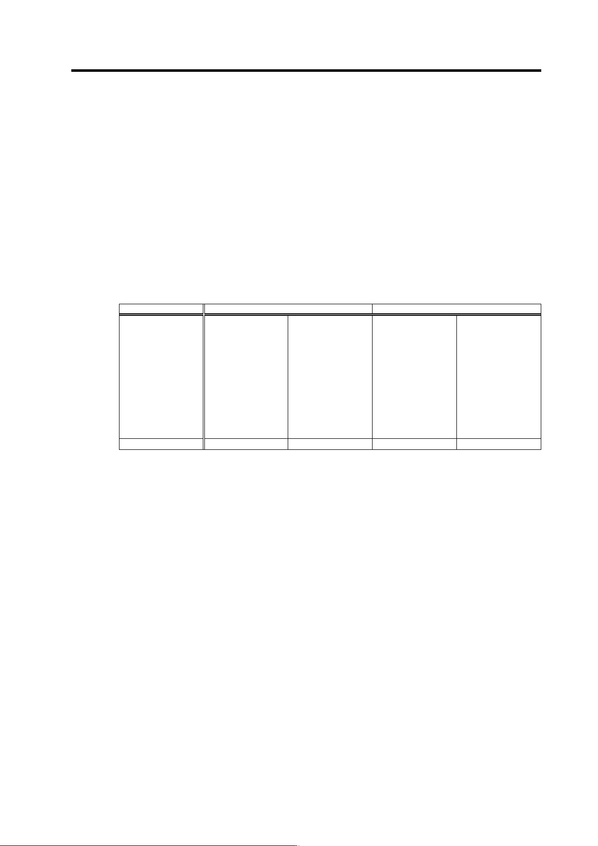
[2] When varying the speed, turn the L coil selection command signal (LCS) ON and OFF as
shown in the following table.
Current coil state When low-speed coil is selected When high-speed coil is selected
Next speed
command
Low-speed coil
range
Does not change
(LCS: ON)
High-speed coil
range
Judge state of SD
signal
[1] SD: ON
→LCS: ON
[2] SD: OFF
→LCS: OFF
Low-speed coil
range
Judge state of SD
signal
[1]SD: ON
→LCS: ON
[2] SD: OFF
→LCS: OFF
High-speed coil
range
Does not change
(LCS: OFF)
Operation mode
[2]-A [2]-B [2]-C [2]-D
(Note) The conditions in item 1) are applied to prevent the contactor from turning ON/OFF needlessly during
acceleration/deceleration.
Since the speed detection signal (SD) has a hysteresis, the conditions in item 2) are applied to prevent the
contactor from turning ON/OFF needlessly (inconsistently) when operating near the coil change speed and
continuously varying the speed.