MDS-C1-SPA Series INSTRUCTION MANUALib1500152(eng)a.pdf - 第32页
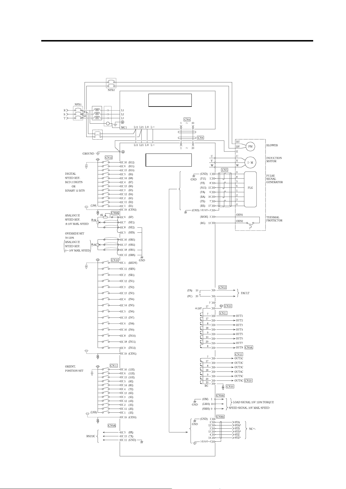
2. Wiring and Connection 2 - 4 2-1-2 Detailed connection diagram (1) With no orientation / When using motor built-in encoder orientation B-AL TYPE MDS-C1-CV - □ TYPE MDS-C1-SP A- □ Contactor NFB3
2. Wiring and Connection
2 - 3
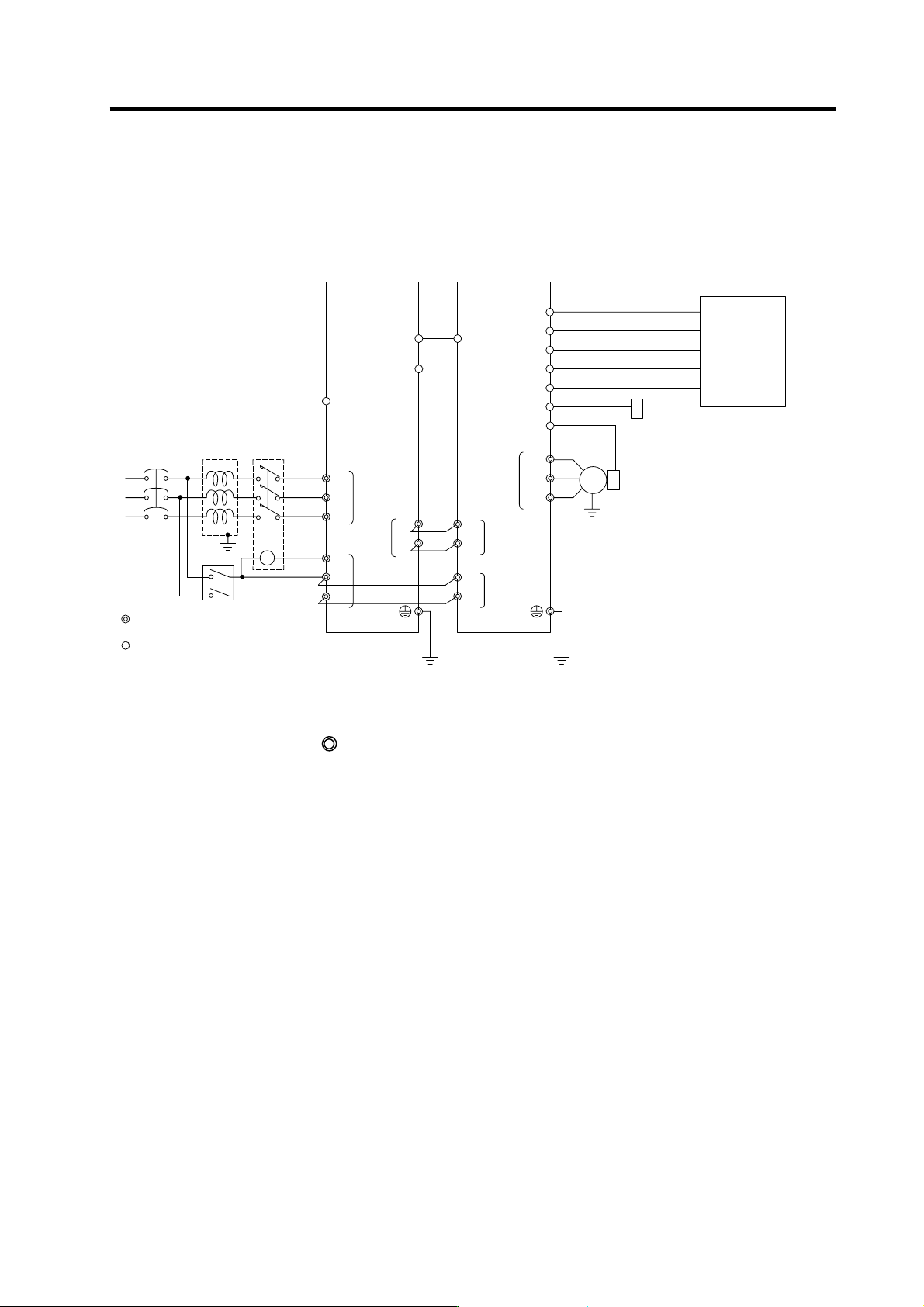
2-1 Connection diagram
2-1-1 Part system connection diagram
MC1
External emergency stop input
T
S
R
Contacto
r
No-fuse
breaker
Ground
: Main circuit
: Control circuit
CN23
CN4
L1
L2
L3
L11
TE3
TE1
CN9
CN12
L+
L-
U
V
W
CN6
CN5
TE1
PLG
Spindle drive unitPower supply unit
Spindle
motor
CN4
TE3
TE2
L+
L-
L11
L21
TE2
AC
reactor
Ground
Ground
L21
CN9A
CN8A
MC
Breake
r
CN11
CN10
ENC
Spindle side detector
S-analog speed command, pulse feedback
Speed
•
load meter, serial I/F
Digital speed command,
general-purpose
•
error output
Orientation position command,
General-purpose output
General purpose, general-purpose output
NC
PC
DIO
Meter
Personal compu te
r
(Note 1) The connection method will differ according to the used motor.
(Note 2) The main circuit (
) and control circuit ({) are safely separated.
2. Wiring and Connection
2 - 4
2-1-2 Detailed connection diagram
(1) With no orientation / When using motor built-in encoder orientation
B-AL
TYPE
MDS-C1-CV-□
TYPE
MDS-C1-SPA-
□
Contactor
NFB3
2. Wiring and Connection
2 - 5
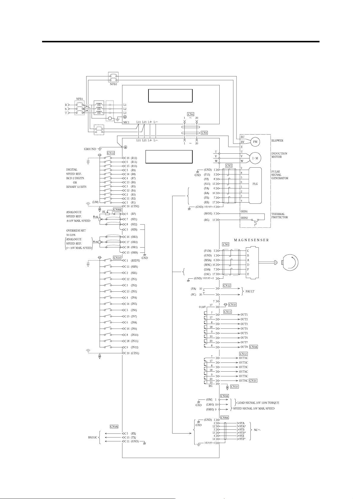
(2) When using magnetic sensor orientation
B-AL Contactor
TYPE
MDS-C1-CV-□
TYPE
MDS-C1-SPA-□
NFB3