MDS-C1-SPA Series INSTRUCTION MANUALib1500152(eng)a.pdf - 第158页
4. Spindle Adjustment 4 - 67 (6) Confirming pulse feedback ou tput signal Pulse feedback signal outp ut from t he spindle drive unit is confirme d. Related parameter Nos. and descriptio ns are as shown below. No. Abbrev …
4. Spindle Adjustment
4 - 66
(4) Adjustment
General adjustment method is described in the following. Note that, however, if the adjustment
method is described in the adjustment manual for the NC to be used, the NC adjustment manual
takes precedence over thi s manu al.
(5) Adjusting the acceleration/deceleration time constant
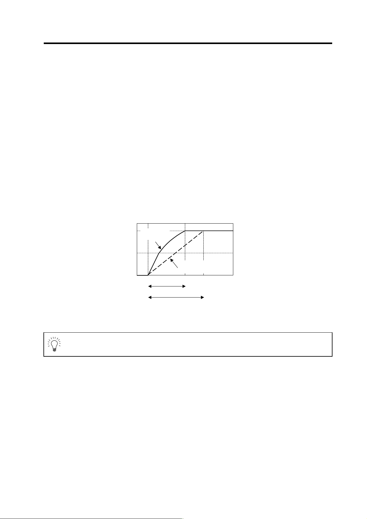
Synchronous tap synchronizes the operation with the servo. Generally, the spindle takes longer to
accelerate and decelerate, so the acceleration/deceleration time constant is determined on the
spindle side. Measure the acceleration time for the S command, and set a value 1.5-fold of the
measured value as the standard value.
If the spindle maximum rotation speed is 2000r/min during synchronous tap operation, first carry
out 2000r/min acceleration/deceleration with the S command as shown below. Then, measure the
total acceleration time in a linear, 2-step or 3-step state. The time constant for synchronous tap
operation is 450ms which is 1.5-fold 300ms.
When the value other than "0000" is set to the spindle parameters SP314 to SP319 or SP378 to
SP383, change the parameter value as follows and turn the spindle drive unit's power ON/OFF or
turn the alarm reset input ON/OFF before collecting the acceleration/deceleration data.
Set the same value as SP314 to SP317, SP315 to SP318, and SP316 to SP319.
Set the same value as SP378 to SP381, SP379 to SP382, and SP380 to SP383.
Upon completion of the measurement, be sure to return the changed parameter value to the
original setting value.
0
1000
2000
Accelerat i on time during S command
Standard accel erati on time duri ng synchronous tap (1. 5-fold)
Measuring the acceleration time during S command
Speed FB
[r/min]
0
300 450 [ms]
During
S command
During synchronous
ta
p
control
POINT
When executing the synchronous tappin g operation with the coil changeover motor,
the coil must be fixed and used. In this case, fix all the coils to be use d one by one,
and carry out S command to measure the acceleration/deceleration time.
4. Spindle Adjustment
4 - 67
(6) Confirming pulse feedback output signal
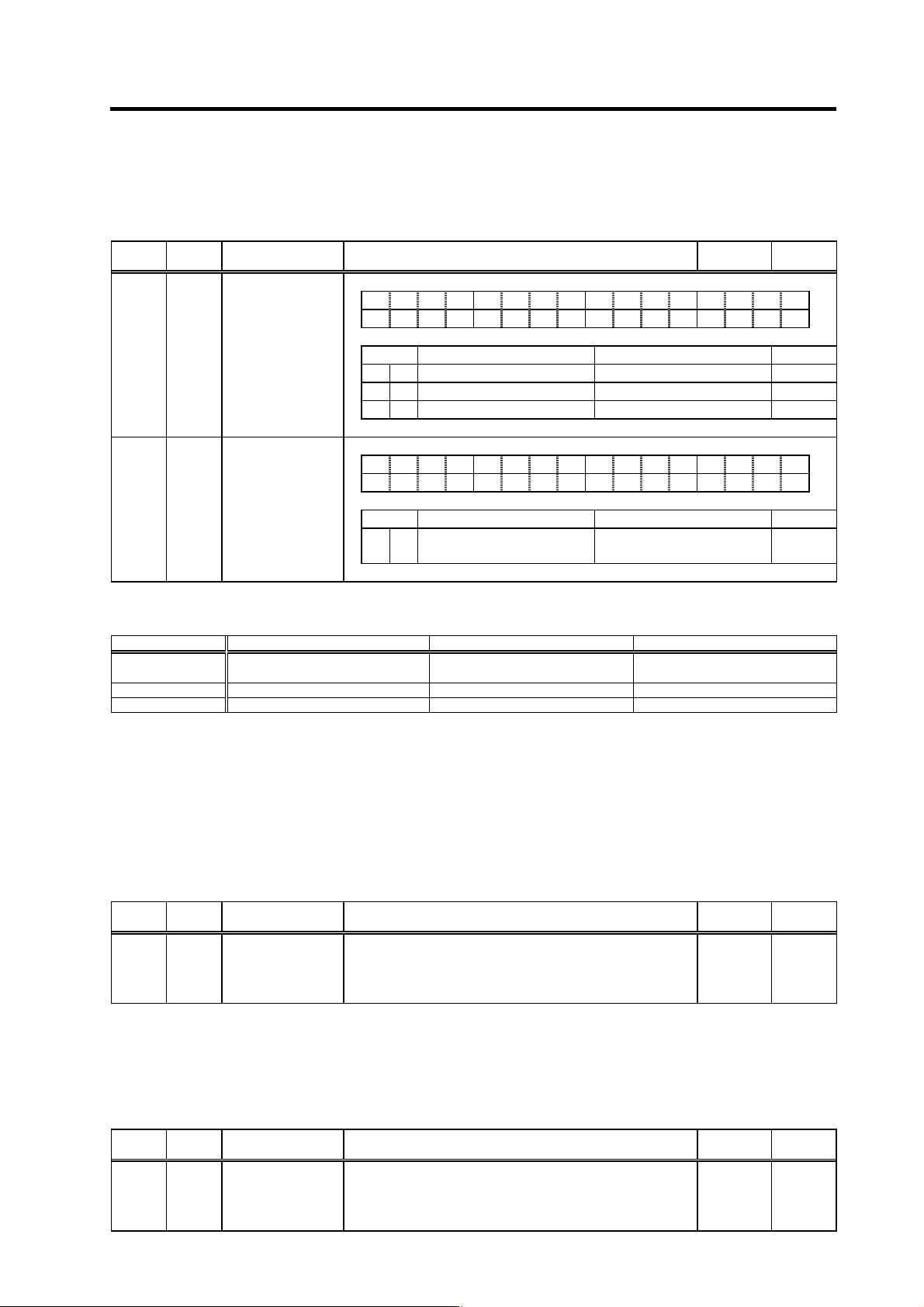
Pulse feedback signal output from the spindle drive unit is confirme d.
Related parameter Nos. and descriptions are as shown below.
No. Abbrev. Parameter name Description
Setting
range
Standard
value
SP037 SFNC5 Spindle function 5
F E D C B A 9 8 7 6 5 4 3 2 1 0
dplg ospcl noplg nsno nosg psdir plgo mago enco
bit Meaning when "0" is set Meaning when "1" is set Standard
0
e
nco Encoder orientation invalid Encoder orientation valid 0
1 mago Magnetic sensor orientation invalid Magnetic sensor orientation valid 0
2 plgo PLG orientation invalid PLG orientation valid 0
SP038 SFNC6 Spindle function 6
F E D C B A 9 8 7 6 5 4 3 2 1 0
oplp lmx iqsv dcsn lmnp vfbs orm plg2 alty
bit Meaning when "0" is set Meaning when "1" is set Standard
3 plg2 Semi-closed pulse output signal×2
invalid
Semi-closed pulse output signal×2
valid
0
The pulse feedback signals with the a bove parameter settings (CN8A-2 to 4, 12 to 14 pi ns) outputs
the following signals.
SP037 setting CN8A-2(SYA), 12(SYA*) CN8A-3(SYB), 13(SYB*) CN8A-4(SYZ), 14(SYZ*)
bit2: "1",
or bit0 to 2: "0"
Motor PLG A phase signal Motor PLG B phase signal
Motor PLG Z phase signal
(Note 1)
bit0: "1" 1024p/rev encoder A phase signal 1024p/rev encoder B phase signal 1024p/rev encoder Z phase signal
bit1: "1" Motor PLG A phase signal Motor PLG B phase signal Magnetic sensor LNZ signal
(Note 1) Z-phase signal will not be output when Z-phase signal is not mounted on the motor PLG.
(Note 2) When "1" is set to SP038 bit3, A-phase and B-phase signals of the motor PLG output doubling the number of pulses per
revolution. (When PLG is 256p/rev, 512p/rev oblong wave is output.)
(Note 3) All the pulse feedback signals are output in oblong wave. For details, refer to the section "2-6-2 Output interface".
(7) Adjusting the analog command offset
Turn the S-analog synchro nou s tapping sign al ON an d confirm the minute vibration when stop ped.
If the vibration is large, set the value of SP158(Adofs) to SP176(HADof) and adjust the value of
SP176(HADof) to minimize the vibration.
Related spindle parameters
No. Abbrev. Parameter name Description
Setting
range
Standard
value
SP176 HADof*
S-analog
high-speed tapping
speed command
offset
Sets the speed command voltage offset value during S-analog
high-speed tapping.
When "0" is set, the value will be the one set in SP158(Adofs).
-999 to 999 0
(8) Adjusting analog command gain
Turn the S analog synchronous tapping signal ON to secure a longer stroke. Carry out dry-run
operation at the highest speed available for synchronous tapping and adjust SP175(HSgn) to gain
the highest desirable spee d.
Related spindle parameters
No. Abbrev. Parameter name Description
Setting
range
Standard
value
SP175 HSgn*
S-analog
high-speed tapping
speed command
gain
Sets the speed command voltage gain during S-analog
high-speed tapping.
When "0" is set, the value will be the one set in SP161(Sgain).
0 to 2500
(1/1000-fold)
0
4. Spindle Adjustment
4 - 68
(9) Synchronous tapping operation
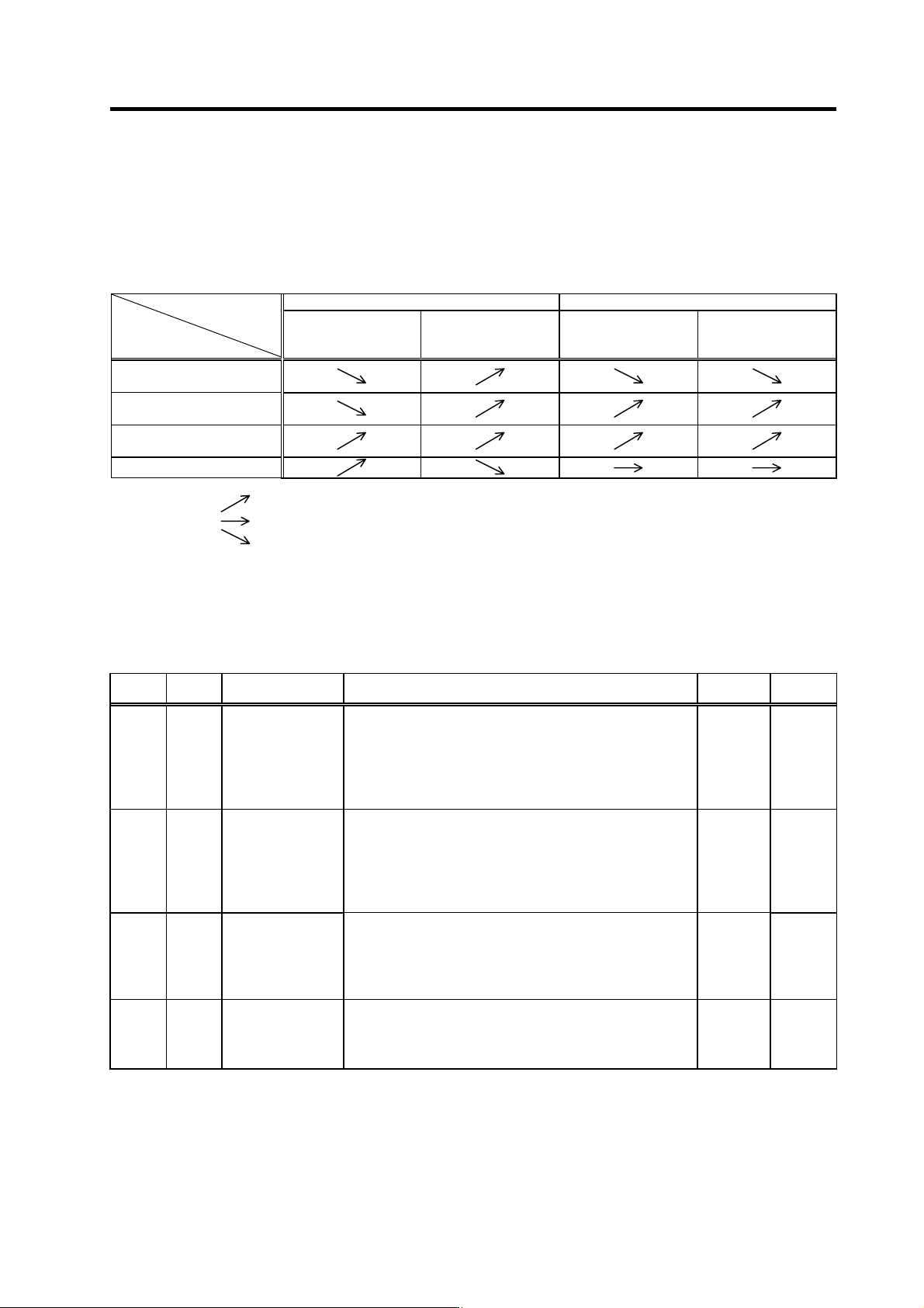
Carry out trial operation after setting the parameters. Carry out dry operation without tapping or a
workpiece, and confirm the amount that the spindle moves in respect to the servo axis. If there is
no problem, proceed with actual cutting operation. If there any problem occurs during dry run
operation or actual cutting operation, refer to the following table and change the settings
accordingly.
NC side setting Spindle drive unit side setting
Position loop gain
Acceleration/
deceleration time
constant
SP172(VGHP)
SP173(VGHI)
SP174(HPYV)
Gear noise is louder than
one in regular operation
The spindle undershoots
or overshoots
Machining accuracy is
poor
Machining time is long
(Note 1) The meaning of the arrows above is as described below.
: Increase the setting value
: Do not change the setting value
: Decrease the setting value
(Note 2) When the gear noise is large in standard setting, and the machining precision deteriorates as the speed loop gain is
decreased, if the motor maximum speed during S analog high-speed tapping is lower than the regular motor maximum
rotation speed, those conditions may be solved by setting a smaller value than SP017(TSP) in SP171(HSPT).
Note that, in this case, the spindle (or the motor) maximum speed during the NC side S analog high-speed tapping must be
changed. Thus, analog speed command offset and analog speed command gain must be adjusted again.
Related spindle parameters
No. Abbrev. Parameter name Description
Setting
range
Standard
value
SP171 HSPT
S-analog
high-speed tapping
motor maximum
speed
Sets the maximum motor speed during S-analog high-speed
tapping.
When "0" is set, the value will be the one set in SP017(TSP).
Sets the maximum motor tapping speed here when the gear
noise is louder than during the regular speed loop operation, or
when you wish to improve the tapping accuracy.
0 to 32767
(r/min)
0
SP172 VGHP
S-analog
high-speed tapping
speed loop
proportional gain
Sets the speed loop proportional gain during S-analog
high-speed tapping.
The larger the value, the higher the responsiveness, but the
bigger the vibration or noise becomes.
When "0" is set, the value will be the one set in
SP022(VGNP1).
0 to 1000 0
SP173 VGHI
S-analog
high-speed tapping
speed loop integral
gain
Set s the speed loop integral gain during S-analog high-speed
tapping
If the value of SP172(VGHP) is set, set the value so that the
setting value’s proportion between SP172 and SP173 is 1:1.
When "0" is set, the value will be the one set in SP023(VGNI1).
0 to 1000 0
SP174 HPYV
S-analog
high-speed tapping
variable excitation
rate (min value)
Sets the minimum value of the variable excitation rate during
S-analog high-speed tapping.
Smaller value is set to suppress the gear noise, etc., and larger
value is set to improve the tapping accuracy.
0 to 100
(%)
0