MDS-C1-SPA Series INSTRUCTION MANUALib1500152(eng)a.pdf - 第171页
4. Spindle Adjustment 4 - 80 (6) Coil changeover contactor (magnetic contact) [1] Selection The coil changeover conta c tor is selected accordi ng to the applicable spi ndle drive unit's capacity as shown below. Spi…

4. Spindle Adjustment
4 - 79
No. Abbrev. Parameter name Description
Setting
range
Standard
value
SP129
to
SP140
HI01
to
HI12
General-purpose input
selection
Set the general-purpose input signals IN1 to IN12 as to which
function they should have. To have the coil changeover function,
set "18" (L coil selection command) in one of those signals.
0 to 21 -
SP141
to
SP154
HO1e
to
HO1c
General-purpose
output selection
Set the general-purpose output signals OUT1 to OUT8 (open
emitter) or OUT1C to OUT6C (open collector) as to which
function they should have. Set "18" (L coil selected signal) in
one of those signals. Also, set "16" (changing coil) in another
signal as required.
0 to 23 -
SP257
to
SP320
Motor constant (H coil)
These parameters are valid only in the following two conditional
cases.
(a) SP034(SFNC2)/bit0=1 and SP034(SFNC2)/bit2=0
Set the motor constants for the special and non-coil
changeover motor not indicated in the explanation of SP040
(MTYP).
(b) SP034(SFNC2)/bit0=1 and SP034(SFNC2)/bit2=1
Set the H coil side motor constants of the coil changeover
motor.
(Note) It is not allowed for the user to change the setting.
(HEX setting)
0000 to
FFFF
0000
SP321
to
SP384
Motor constant (L coil)
These parameters are valid only in the following case.
(a) SP034(SFNC2)/bit0=1 and SP034(SFNC2)/bit2=1
Set the L coil side motor constants of the coil changeover
motor.
(Note) It is not allowed for the user to change the setting.
(HEX setting)
0000 to
FFFF
0000
4. Spindle Adjustment
4 - 80
(6) Coil changeover contactor (magnetic contact)
[1] Selection
The coil changeover contac tor is selected according to the applicable spindle drive unit's capacity
as shown below.
Spindle drive unit type Applicable contactor type Spindle drive unit type Applicable contactor type
MDS-A/B-SPA(H)-040 S-N10 MDS-A/B/C1-SPA(H)-150 S-N50
MDS-A/B-SPA(H)-075 S-N10 MDS-A/B/C1-SPA(H)-185 S-N65
MDS-A/B-SPA(H)-15 S-N10 MDS-A/B/C1-SPA(H)-220 S-N80
MDS-A/B-SPA(H)-22 S-N10 MDS-A/B/C1-SPA(H)-260 S-N80
MDS-A/B-SPA(H)-37 S-N18 MDS-A/B/C1-SPA(H)-300 S-N125
MDS-A/B/C1-SPA(H)-55 S-N20 MDS-B-SPA(H)-370 S-N150
MDS-A/B/C1-SPA(H)-75 S-N25 MDS-B-SPA(H)-450 S-N180
MDS-A/B/C1-SPA(H)-110 S-N35 MDS-B-SPA(H)-550 S-N300
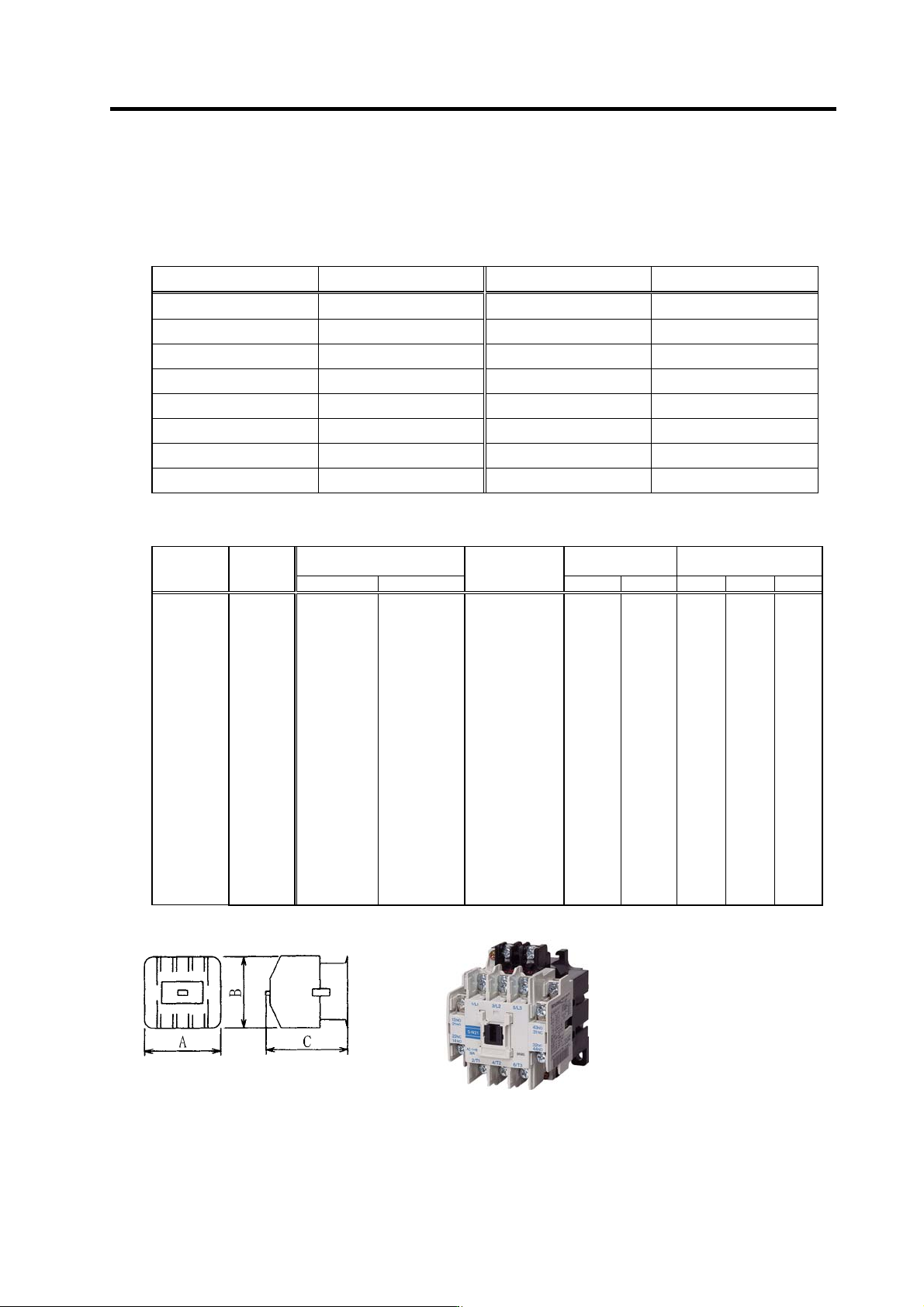
[2] Outline
AC Class 3 rated working
current (A)
Support contact Dimensions (mm)
Name Model
200 to 220V 380 to 440V
Rated
conductivity
current (A)
Standard Special A B C
Open type
Non-
reversible
type
S-N10
S-N11
S-N12
S-N18
S-N20
S-N21
S-N25
S-N35
S-N50
S-N65
S-N80
S-N95
S-N125
S-N150
S-N180
S-N220
S-N300
S-N400
S-N600
S-N800
11
13
13
18
20
20
26
35
50
65
80
100
125
150
180
220
300
400
630
800
7
9
9
13
20
20
25
32
48
65
80
93
120
150
180
220
300
400
630
800
20
20
20
25
32
32
50
60
80
100
135
150
150
200
260
260
350
450
660(800)
800(1000)
1a
1a
1a1b
—
1a1b
2a2b
2a2b
2a2b
2a2b
2a2b
2a2b
2a2b
2a2b
2a2b
2a2b
2a2b
2a2b
2a2b
2a2b
2a2b
1b
1b
2a
—
2a
—
—
—
—
—
4a4b
4a4b
4a4b
4a4b
4a4b
4a4b
4a4b
4a4b
4a4b
4a4b
43
43
53
43
63
63
75
75
88
88
100
100
100
120
138
138
163
163
290
290
78
78
78
79
81
81
89
89
106
106
124
124
150
160
204
204
243
243
310
310
78
78
78
81
81
81
91
91
106
106
127
127
136
145
174
174
195
195
234
234
S-N21 type

5 - 1
5. Troubleshooting
5-1 Points of caution and confirmation ................................................................................................... 5-2
5-1-1 LED display when alarm or warning occurs .............................................................................. 5-3
5-2 Protective functions list of units ........................................................................................................ 5-4
5-2-1 List of alarms.............................................................................................................................. 5-4
5-2-2 List of warnings .......................................................................................................................... 5-6
5-3 Troubleshooting ................................................................................................................................ 5-7
5-3-1 Troubleshooting at power ON.................................................................................................... 5-7
5-3-2 Troubleshooting for each alarm No. .......................................................................................... 5-8
5-3-3 Troubleshooting for each warning No......................................................................................5-21
5-3-4 Troubleshooting the spindle system when there is no alarm or warning................................. 5-22