MDS-C1-SPA Series INSTRUCTION MANUALib1500152(eng)a.pdf - 第93页
4. Spindle Adjustment 4 - 2 4-1 D/A output specificati ons for spindle drive unit The spindle drive unit has a function to D/A output each control data. The spindle adju stment data required to set the spindle paramete r…

4 - 1
4. Spindle Adjustment
4-1 D/A output specifications for spindle drive unit................................................................................. 4-2
4-1-1 D/A output specifications ........................................................................................................... 4-2
4-1-2 Setting the output data............................................................................................................... 4-2
4-1-3 Setting the output magnification ................................................................................................ 4-3
4-2 Spindle control signal........................................................................................................................ 4-5
4-2-1 Spindle control input (NC to SP) ................................................................................................ 4-5
4-2-2 Spindle control output (SP to NC)............................................................................................ 4-15
4-3 Adjustment procedures for each control......................................................................................... 4-27
4-3-1 Basic adjustments.................................................................................................................... 4-27
4-3-2 Adjusting the acceleration/deceleration operation................................................................... 4-30
4-3-3 Adjusting the orientation control .............................................................................................. 4-39
4-3-4 Adjusting the multi-point indexing orientation control .............................................................. 4-55
4-3-5 Adjusting S-analog high-speed tapping control ....................................................................... 4-64
4-3-6 Adjusting coil changeover........................................................................................................ 4-69
4. Spindle Adjustment
4 - 2
4-1 D/A output specifications for spindle drive unit
The spindle drive unit has a function to D/A output each control data. The spindle adjustment data
required to set the spindle parameters matching the machine can be D/A output. The data can be
measured with a hi-corder or oscilloscope, etc.
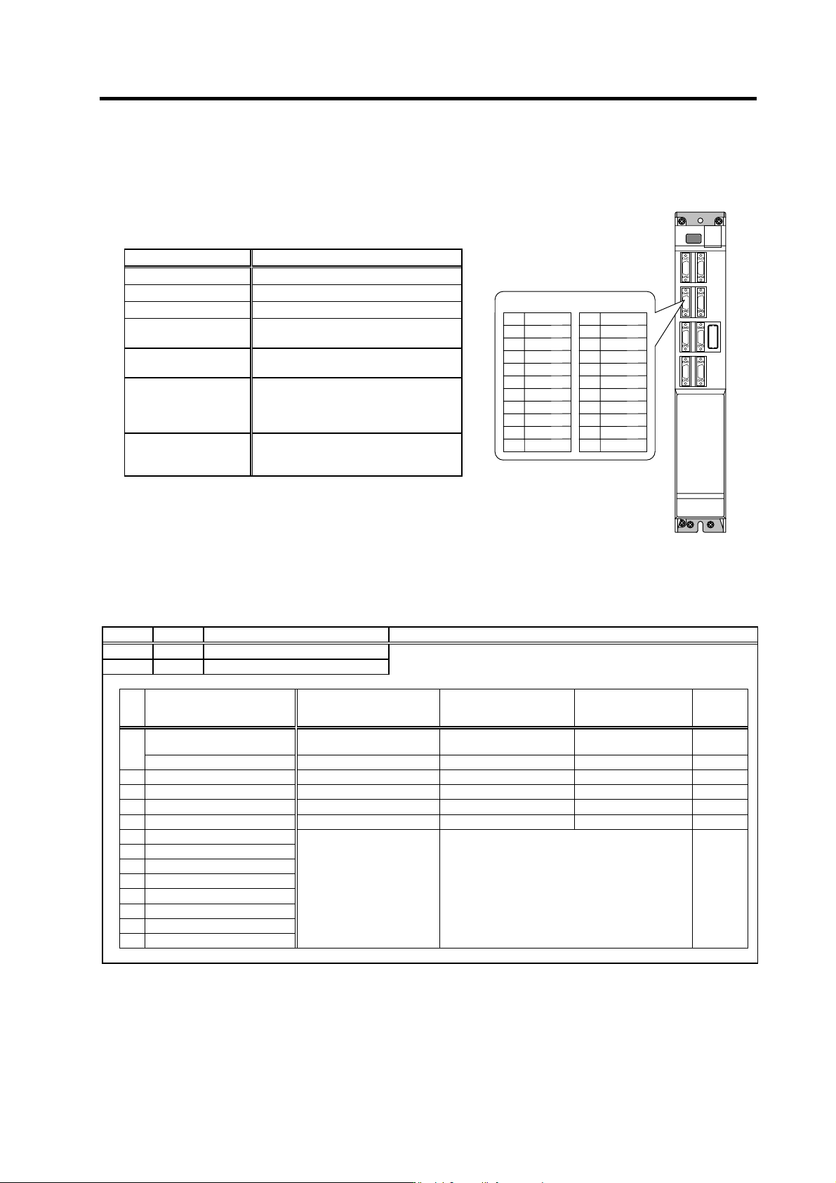
4-1-1 D/A output specifications
4-1-2 Setting the output data
No. Abbr. Parameter name Explanation
SP253 DA1NO
D/A output channel 1 data No.
Input the No. of the data to be output to each D/A output channel.
SP254 DA2NO
D/A output channel 2 data No.
No. Output data Original data unit
Output magnification
standard setting value
(SP255, SP256)
Output unit for
standard setting
Output
cycle
ch1: Speedometer output 10V=max. speed (Zero=0V) 0
Depends on maximum
speed
3.55ms
0
ch2: Load meter output 10V=120% load (Zero=0V) 0 30-minute rating 12%/V 3.55ms
1 –
2 Current command Rated 100%=4096 8 30-minute rating 20%/V 3.55ms
3 Current feedback Rated 100%=4096 8 30-minute rating 20%/V 3.55ms
4 Speed feedback r/min 13 500rpm/V 3.55ms
80 Control input 1
81 Control input 2
82 Control input 3
83 Control input 4
84 Control output 1
HEX Bit correspondence 3.55ms
85 Control output 2
86 Control output 3
87 Control output 4
Item Explanation
No. of channels 2ch
Output cycle 444µs (min. value)
Output precision 8bit
Output voltage range
0V to +5V (zero) to +10V,
0V to +10V for meter output
Output magnification
setting
±1/256 to ±128-fold
Output pin
CN9 connector
SMO = Pin 9 (D/A channel1)
LMO = Pin 19 (D/A channel2)
GND = Pin 1
Function
Phase current feedback output function
IU (U phase current FB) : Pin 7
IV (V phase current FB) : Pin 17
SMO9
Name
GND
IU
2
5
1
Pin
6
4
3
10
7
8
CN9 connector
LMO 19
Name
IV
12
15
11
Pin
16
14
13
20
17
18
4. Spindle Adjustment
4 - 3
4-1-3 Setting the output magnification
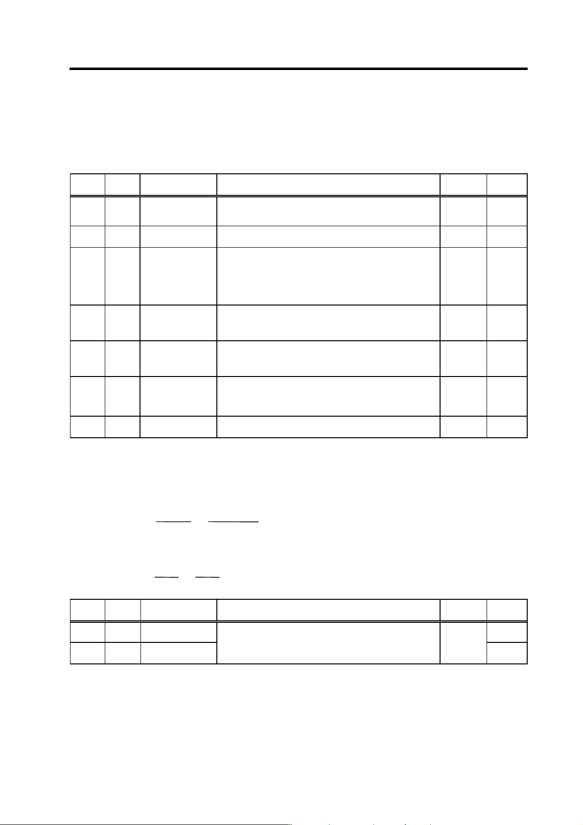
(1) Meter output (Data No. 0)
With meter output, the output channel is fixed, and the output voltage range is 0 to 10V in the
positive range. Set the magnification with the following parameters. Also, low path filter can be set
on the load meter output.
No. Abbr. Parameter name Details
Setting
range
Standard
SP017 TSP* Maximum motor
speed
Set the maximum spindle motor speed.
When SP249=0, the motor speed will be the motor rotation
speed at the speedometer 10V output.
1 to 32767
(r/min)
6000
SP094 LMAV* Load meter output
filter
Set the filter time constant of load meter output.
When "0" is set, a filter time constant is set to 226ms.
0 to 32767
(3.5ms)
0
SP177
MADJ*
Meter full scale
compulsory output
When carrying out a full-scale adjustment to the speed meter
and load meter, set to "1" here so that the full scale voltage is
output and the adjustment mode is entered. Adjustment is
carried out with SP178(SMG) and SP179(LMG) at this time.
Always return the setting value to "0" when the adjustment is
completed.
0 to 1 0
SP178 SMG*
Speed meter output
full scale adjustment
Adjust the speed meter full scale.
Adjust so that the fluctuations of the speed meter is at the
intended position when "1" is set in SP177(MADJ).
0 to 1000
(1/1000-fold)
938
SP179 LMG*
Load meter output
full scale adjustment
Adjust the load meter full scale.
Adjust so that the fluctuations of the load meter is at the
intended position when "1" is set in SP177(MADJ).
0 to 1000
(1/1000-fold)
938
SP249 SMO Speedometer speed Set the motor rotation speed when the speedometer 10V is
output.
When set to "0", this parameter becomes the same as SP017
(TSP).
0 to 32767
(r/min)
0
SP250 LMO Load meter voltage Set the voltage when the load meter 120% is output. When set
to "0", this becomes 10V.
0 to 10
(V)
0
(2) Internal data output (Data No. 1 to 13)
Normally, the standard setting value is set for the output magnification (SP255, SP256). When
"0" is set, the magnification will be the same as "256".
DATA ×
SP255
256
×
10 [V]
256
(
8 bit
)
+ 5 [V] (offset) = Output voltage [V]
(Example) To output current FB at a 30-minute stall rating 20%/V unit (SP253=3, SP255=8)
819.2 ×
8
256
×
10
256
+ 5 = 6 [V]
No. Abbr. Parameter name Details
Setting
range
Standard
SP255 DA1MPY DA output channel 1
magnification
0
SP256 DA2MPY DA output channel 2
magnification
Set the output magnification with a 1/256 unit.
When "0" is set, the magnification will be the same as "256".
-32768 to
32767
(1/256-fold)
0