MDS-C1-SPA Series INSTRUCTION MANUALib1500152(eng)a.pdf - 第120页
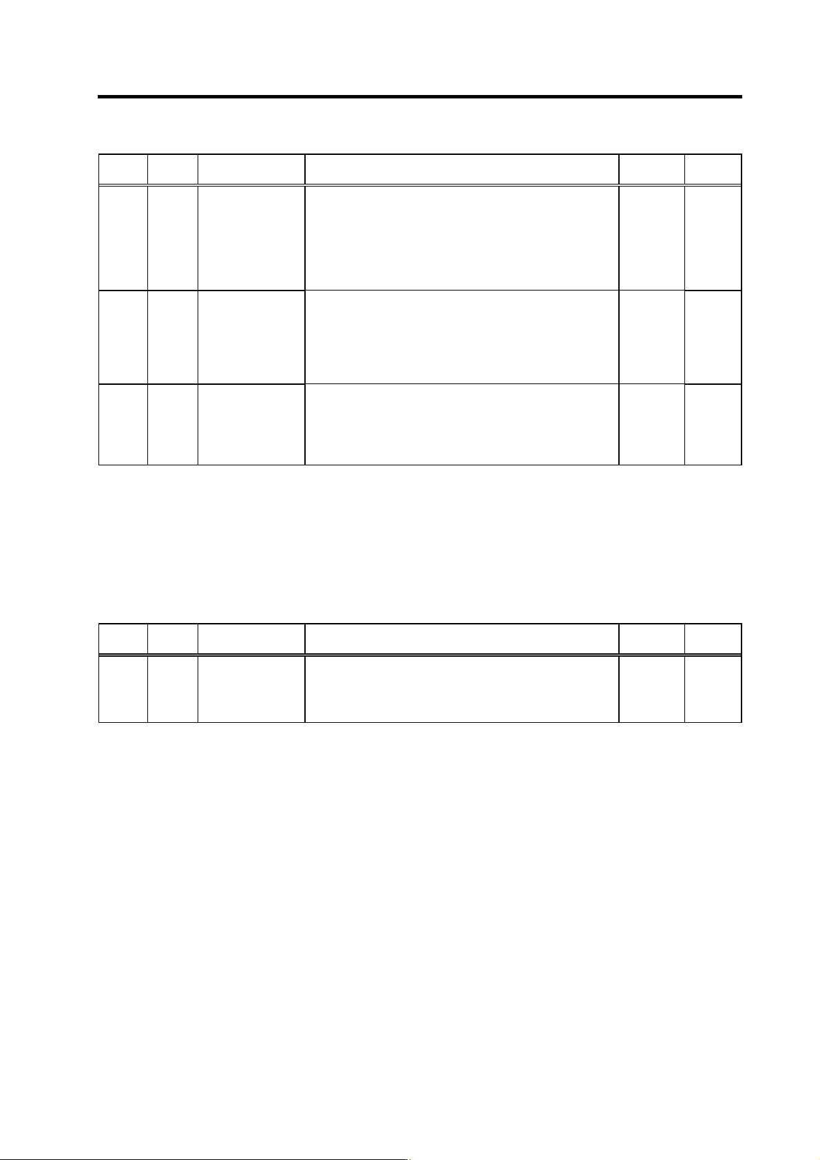
4. Spindle Adjustment 4 - 29 No. Abbr. Parameter name Details Setting range Standard SP155 SAtyp S analog speed command input type Select where to input the S analog input. [0]: Input between SE1(CN8A-7 pi n) and SE2(CN8…

4. Spindle Adjustment
4 - 28
(3) Adjusting the motor (spindle) rotation speed
(a) When using analog input for the speed command
1) When using bipolar input (SE1-SE2 input) for the speed command
[1] Confirm if "0" is set to the parameter SP155(SAtyp) and SP158(Adofs), and "1053" to
SP161(Sgain).
[2] Start the motor by commanding SO(0 rotation comm and) from NC(PC).
[3] Adjust the value of SP158(Adofs) so that the motor(spindle) almost stops.
The motor (spindle) rotation may not be stopped completely even if SP158(Adofs) is adjusted.
[4] Start the motor by inputting S*** from NC(PC).
At this time, S*** equals to the value "maximum spindle speed×0.95" (Motor speed =
S***×(1/gear ratio))
[5] Adjust SP161(Sgain) so that the motor (spindle) rotation speed becomes the speed set in [4]
above.
S command rot. speed
S command rot. speed x (1/gear ratio)
Motor actual rotation speed
Spindle actual rotation speed
SP161(Sgain)
≒1053 x
or
[6] After following all the setting procedures above, change the S command and confirm if the
rotation speed changes ac cordingly.
2) When using unipolar input (OR1-O R2 input) for the speed command
[1] Confirm if "1" is set to the parameter SP155(SAtyp), "262" to SP158(Adofs), and "1147" to
SP161(Sgain).
[2] Start the motor by commanding SO from NC(PC).
[3] Adjust SP158 so that the motor (spindle) is stopped.
Subtract "1" from the value at which the motor (spindle) starts rotating from a stop state, and
then set that value in SP158(Adofs).
(Example)
SP158(Adofs) = "257" : Motor (spindle) stops
SP158(Adofs) = "258" : Motor (spindle) starts rotating
The setting value of SP158(Adofs) = "257"
[4] Start the motor by inputting S*** from NC(PC).
At this time, S*** equals to the value "maximum spindle speed×0.95" (Motor speed =
S***×(1/gear ratio))
[5] Adjust SP161(Sgain) so that the motor (spindle) rotation speed becomes the speed set in [4]
above.
S command rot. speed
S command rot. speed x (1/gear ratio)
Motor actual rotation speed
Spindle actual rotation speed
SP161(Sgain)
≒1147 x
or
[6] After following all the setting procedures above, change the S command and confirm if the
rotation speed changes ac cordingly.
4. Spindle Adjustment
4 - 29
No. Abbr. Parameter name Details
Setting
range
Standard
SP155 SAtyp S analog speed
command input type
Select where to input the S analog input.
[0]: Input between SE1(CN8A-7 pin) and SE2(CN8A-8 pin)
(Standard)
(Bipolar input: Possible to input 0 to ±10V)
[1]: Input between OR2(CN8A-17 pin) and SE1(CN8A-18 pin)
(Unipolar input: Possible to input 0 to +10V only)
Note that when "1" is set, the over writing function cannot be
used.
0 to 1 0
SP158 Adofs* S analog speed
command input
offset
Set the offset value of the S analog speed command input. Set
the value so that the spindle almost stops when the input
command is "0".
Note that the rotation of the spindle motor may not be stopped
in full with this setting.
This value fluctuates depending on the usage tim e and ambient
temperature.
-999 to 999
When
SP155=0:
0
When
SP155=1:
262
SP161 Sgain* S analog speed
command input gain
Set the S analog speed command input gain. Set so that the
motor runs at the highest speed when the maximum speed
command is input. 0 to 2500
(1/1000-fold)
When
SP155=0:
1053
When
SP155=1:
1147
(b) When using digital speed command input for the speed command
No adjustment required. Confirm the following items.
1) Confirm if the drive unit type is correct. (Is "D" marked at the end of capacity in dication of the drive
unit type?)
2) Confirm if the setting value of the parameter SP156(DGtyp) is correct.
No. Abbr. Parameter name Details
Setting
range
Standard
SP156 DGtyp Digital speed
command input type
Set the digital speed command input method.
"0": Signed binary
"1": No sign 12-bit binary
"2": BCD2 digits
"3": BCD3 digits
0 to 3 0
4. Spindle Adjustment
4 - 30
4-3-2 Adjusting the acceleration/deceleration operation
(1) Calculating the theoretical acceleration/deceleration time
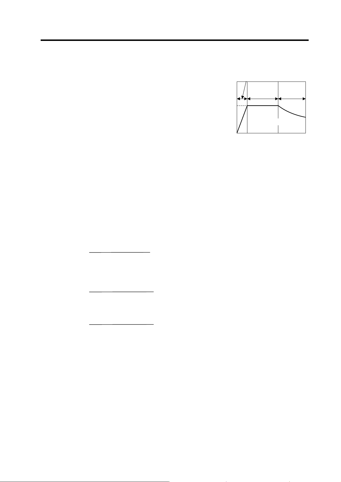
Each theoretical acceleration/deceleration time is calculated
for each output range based on the spin dle motor output
characteristics as shown o n the right. Note that the load
torque (friction torque, etc.) is 0 in the calcul ation expression,
so the acceleration/deceleration time can be known as a
rough guide, but this calculation re sult differs from the
acceleration/deceleration time of the actual machine.
(a) Maximum motor output during
acceleration/deceleration: Po
During acceleration/deceleration, the motor can output at
120% of the short-time rating. Thus, the motor output Po
in the output range during acceleration/deceleration
follows the expression below.
Po = (Short-time rated output) × 1.2 [W]
(b) Total load GD
2
: GD
2
GD
2
of the total load which is accelerated and decelerated follows the expression below.
GD
2
= (Motor GD
2
) + (motor shaft conversion load GD
2
) [kg•m
2
] (Note 1)
The acceleration/deceleration time until the rotation speed "N" to be required is calculated for
each motor output range as shown below, usin g the values obtained in (a) and (b).
(c) Acceleration/deceleration time for constant torque range: t1···0→N [r/min] (0≤N≤N1)
(For N>N1, apply N=N1 and calculate t2 or t3.)
t1 =
1.03 × GD
2
× N1 × N
375 × Po
[s] (Note 1)
(d) Acceleration/deceleration time for constant output range: t2···N1→N [r/min] (N1≤N≤N2)
(For N>N2, apply N=N2 and calculate t3.)
t2 =
1.03 × GD
2
× (N
2
- N1
2
)
2 × 375 × Po
[s] (Note 1)
(e) Acceleration/deceleration time in deceleration output range: t3···N2→N [r/min]
(N2≤N≤N3)
t3 =
1.03 × GD
2
× (N
3
- N2
3
)
3 × 375 × Po × N2
[s] (Note 1)
Based on the above expressions, the acceleration/deceleration time: t from 0 to N3 [r/min] is:
t = t1 + t2 + t3 [s] (Note 2)
(Note 1) Note that "GD
2
" is four times the inertia(J).
(Note 2) If the AC input power voltage to the power supply is low, or if the input power
impedance is high, the acceleration/deceleration time may be long. (Especially, the
acceleration/deceleration time of the deceleration output range ma y be long.)
Output [W]
Output characteristics for
acceleration/deceleration
0N1
N2
0
N3
Po
Rotation speed [r/min]
Short-time rating × 1.2
Constant
output range
Constant out
p
ut ran
g
e
Deceleration
range