MDS-C1-SPA Series INSTRUCTION MANUALib1500152(eng)a.pdf - 第20页
1. Installation 1 - 5 1-2-4 Panel installation hole work drawings (Panel cut draw ings) Prepare a square hole to match the unit width. [Unit: mm] 342 360 82 2-M5 screw Square hole (Note 1) 342 360 1 12 2-M5 screw Square …
1. Installation
1 - 4
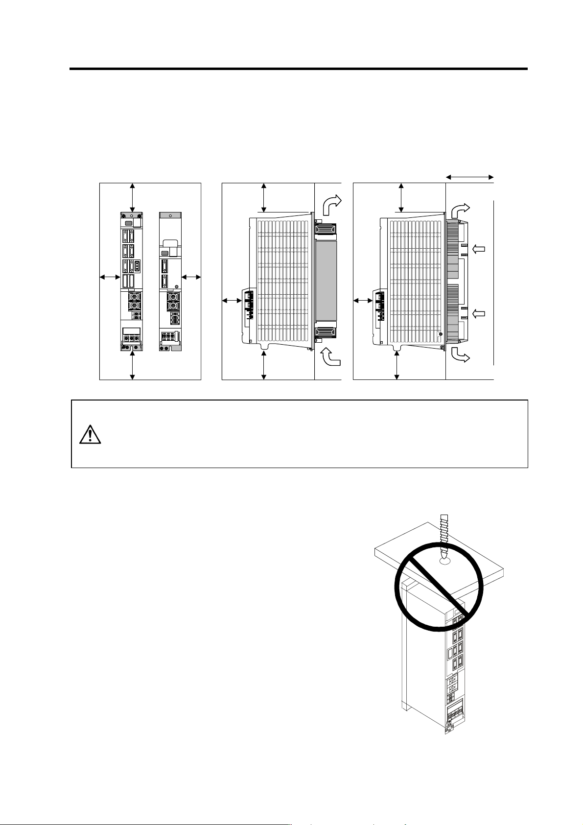
1-2-2 Installation direction and clearance
Wire each unit in consideration of the maintainability and the heat dissipation, as well as secure
sufficient space for ventilation.
100mm or
more
100mm or
more
10mm
or
more
100mm or
more
100mm or
more
50mm
or more
100mm or
more
100mm or
more
75mm or more
50mm
or more
10mm
or
more
CAUTION
The ambient temperature condition for the power supply unit or the drive units is
55°C or less. Because heat can easily accumulate in the upper portion of the
units, give sufficient consideration to heat dissipation when designing the panel.
If required, install a fan in the panel to agitate the heat in the upper portion of the
units.
1-2-3 Prevention of entering of foreign matter
Treat the cabinet with the following items.
• Make sure that the cable inlet is dust and oil proof by using
packing, etc.
• Make sure that the external air does not enter inside by
using head radiating holes, etc.
• Close all clearances.
• Securely install door packing.
• If there is a rear cover, always apply packing.
• Oil will tend to accumulate on the top. Take special
measures such as oil-proofing to the top so that oil does
not enter the cabinet from the screw holds.
• After installing each unit, avoid machining in the periphery.
If cutting chips, etc., stick onto the electronic parts, trouble
may occur.
• When using the unit in an area with toxic gases or high
levels of dust, protect the unit with air purging (system to
blow clean air so that the panel's inner pressure is higher
than the outer pressure).
1. Installation
1 - 5
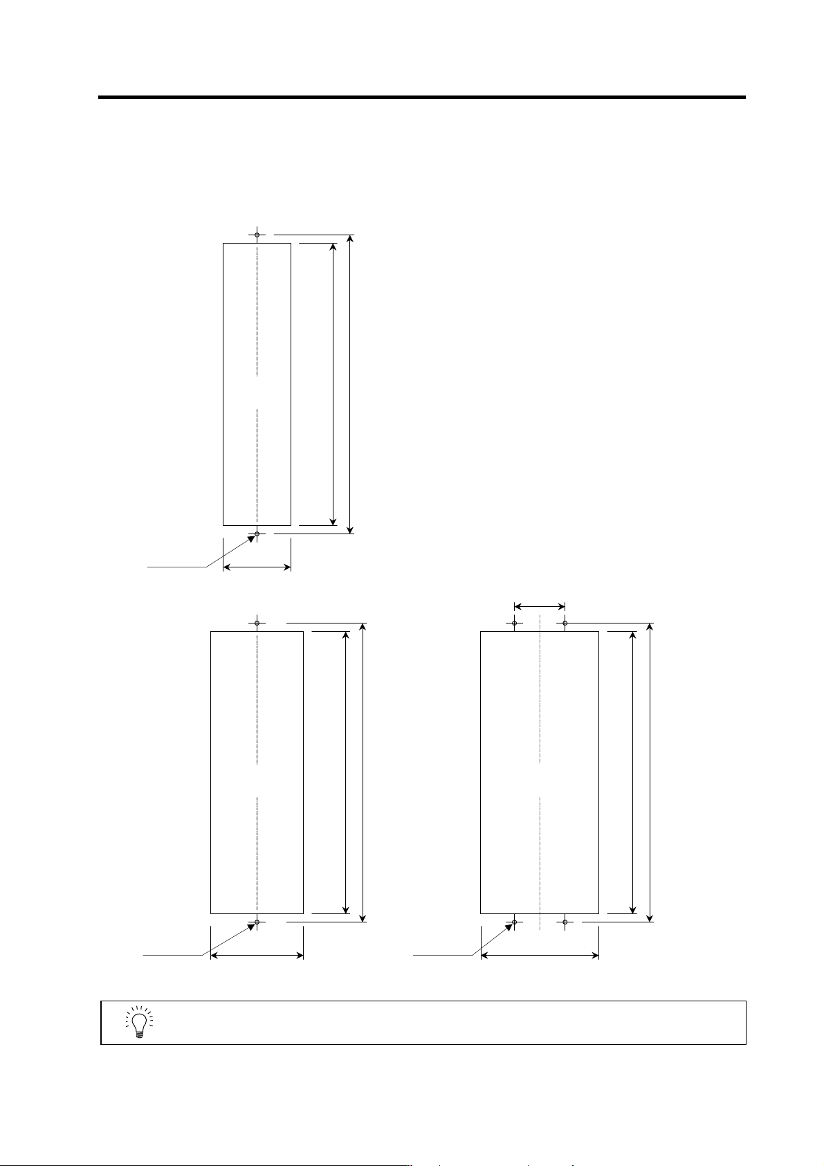
1-2-4 Panel installation hole work drawings (Panel cut drawings)
Prepare a square hole to match the unit width.
[Unit: mm]
342
360
82
2-M5 screw
Square hole
(Note 1)
342
360
112
2-M5 screw
Square hole
(Note 1)
342
360
142
4-M5 screw
60
Square hole
(Note 1)
Unit width: 90mm
Unit width: 120mm Unit width: 150mm
POINT
Attach p acking around the square hole to provide a seal.
1. Installation
1 - 6
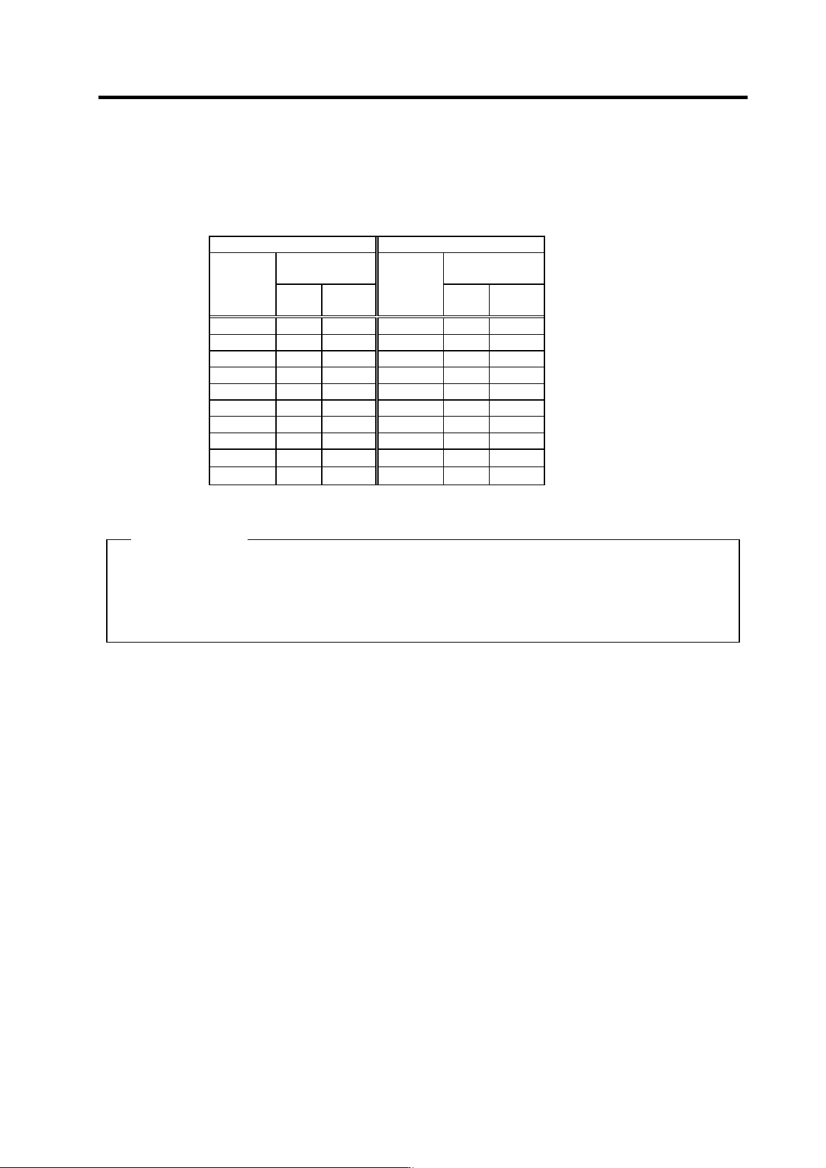
1-2-5 Heating value
Each heating value is calculated with the following values.
The values for the spindle drive unit are for a continuous rated output. The value for the power supply
unit includes the AC reactor's heating value.
Servo drive unit Power supply unit
Heating amount
[W]
Heating amount
[W]
Type
MDS-C1-
Inside
panel
Outside
panel
Type
MDS-C1-
Inside
panel
Outside
panel
SPA- 55 31 76 CV- 37 21 34
SPA- 75 35 102 CV- 55 23 42
SPA-110 41 140 CV- 75 25 55
SPA-150 48 187 CV-110 26 99
SPA-185 62 280 CV-150 29 126
SPA-220 65 301 CV-185 33 162
SPA-260 80 403 CV-220 35 175
SPA-300 98 522 CV-260 40 220
CV-300 46 274
CV-370 54 346
(Example 1)
When using MDS-C1-CV-185, MDS-C1-SPA[]-185[]
Total heating value = (33+162) + (62+280)
= 537 [W]
Heating value in panel = (33) + (62)
= 95 [W]