MDS-C1-SPA Series INSTRUCTION MANUALib1500152(eng)a.pdf - 第77页
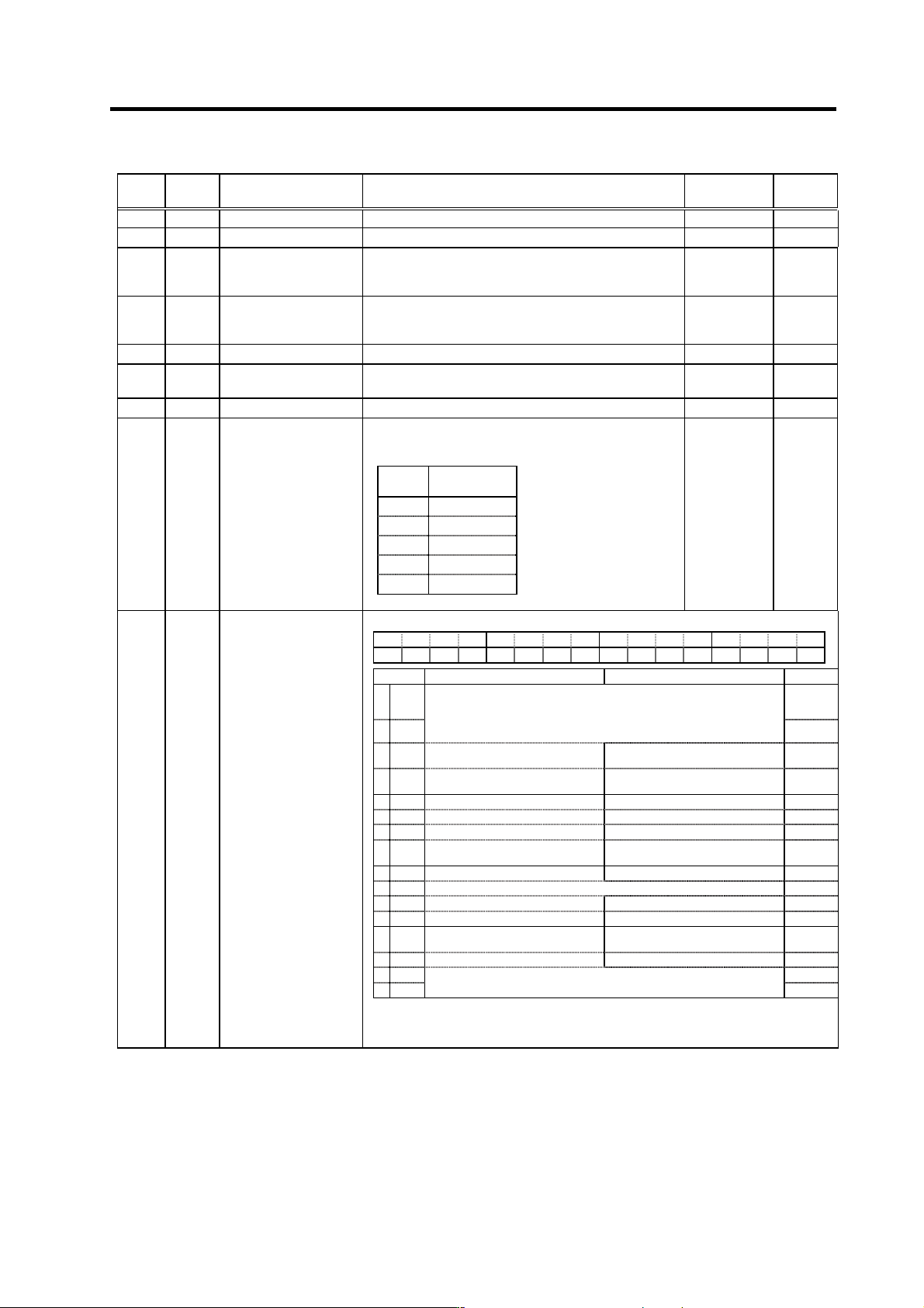
3. Setup 3 - 17 No. Abbr. Parameter name Details Setting rang e (Unit) Standard setting SP098 VGOP Speed loop gain proportional term in orientation control mode Set the speed loop proportional gain in orientation control…
3. Setup
3 - 16
No. Abbr. Parameter name Details
Setting range
(Unit)
Standard
setting
SP089 Not used. Set "0". 0 0
SP090 Not used. Set "0". 0 0
SP091 OFSN*
Offset compensation
during motor PLG
forward run
Set the PLG offset for forward run.
Normally "0" is set.
-2048 to 2047
(-1mV)
0
SP092 OFSI*
Offset compensation
during motor PLG
reverse run
Set the PLG offset for reverse run.
Normally "0" is set.
-2048 to 2047
(-1mV)
0
SP093 Not used. Set "0". 0 0
SP094 LMAV Load meter output filter
Set the filter time constant of load meter output.
When "0" is set, a filter time constant is set to 226ms.
0 to 32767
(3.5ms)
0
SP095 VFAV Fixed control constant Set by Mitsubishi. Set "0" unless designated in particular. 0 0
Set the gear ratio between the spindle side and the
detector side (except for the motor PLG) as indicated
below.
Setting
value
Gear ratio
(deceleration)
0 1 : 1
1 1 : 1/2
2 1 : 1/4
3 1 : 1/8
4 1 : 1/16
SP096 EGAR Encoder gear ratio
-3 to 4 0
F E D C B A 9 8 7 6 5 4 3 2 1 0
ostp orze ksft gchg zdir vg8x mdir fdir oscl pyfx dmin odi2 odi1
bit Meaning when set to 0 Meaning when set to 1 Standard
0 odi1 0
1 odi2
Orientation rotation direction
00: Previous (the direction in which the motor has so far rotated under
speed control)
10: Backward rotation
01: Forward rotation 11: Prohibited
0
2dmin
Orientation completion advance
invalid
Orientation completion advance
valid
0
3pyfx
Excitation min. (50%) during
orientation servo lock invalid
Excitation min. (50%) during
orientation servo lock valid
0
SP097 SPECO Orientation specification
4 oscl Indexing speed clamp invalid Indexing speed clamp valid 0
5 fdir Encoder installation polarity: + Encoder installation polarity: - 0
6 mdir Magnetic sensor polarity: + Magnetic sensor polarity: - 0
7vg8x
Speed gain *1/8 during torque limit
valid
Speed gain *1/8 during torque limit
invalid
0
8 0
9 zdir This is used by Mitsubishi. Set to "0" unless particularly designated. 0
A 0
B 0
Cgchg
Gain changeover during orientation
invalid
Gain changeover during orientation
valid
0
D ksft Orientation virtual target shift invalid Orientation virtual target shift valid 0
Eorze 0
Fostp
This is used by Mitsubishi.
Set to "0" unless particularly designated.
0
(Note ) Set 0 if there is no particular explanation for the bit.
Parameters having an abbreviation with "*" (OFSN*, etc.) are validated right after the settings are changed by the personal
computer, without turning the spindle drive unit's power ON and OFF.
3. Setup
3 - 17
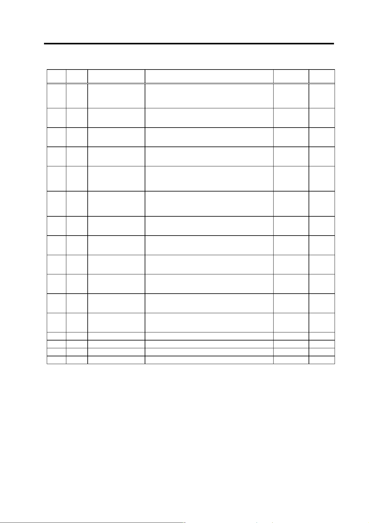
No. Abbr. Parameter name Details
Setting range
(Unit)
Standard
setting
SP098 VGOP
Speed loop gain
proportional term in
orientation control mode
Set the speed loop proportional gain in orientation control
mode.
When the gain is increased, rigidity is improved in the
orientation stop but vibration and sound become larger.
0 to 1000 63
SP099 VGOI
Orientation control mode
speed loop gain integral
term
Set the speed loop integral gain in orientation control
mode. 0 to 1000 60
SP100 VGOD
Orientation control mode
speed loop gain delay
advance term
Set a loop gain delay advance gain in orientation control
mode.
When this parameter is set to "0", PI control is applied.
0 to 1000 15
SP101 DINP
Orientation advance
in-position width
When using the orientation completed advance function,
set the in-position width that is larger than the normal
in-position width defined in SP004 (OINP).
1 to 2880
(1/16 deg)
16
SP102 OODR
Excessive error value in
orientation control mode
Set the excessive error detection width in orientation
control mode.
0 to 32767
(1/4 pulse)
(1 pulse=
0.088 deg)
32767
SP103 FTM
Index positioning
completion OFF time
timer
Set the time for forcedly turn OFF the index positioning
completion signal (different from the orientation
completion signal) after the leading edge of the indexing
start signal.
0 to 10000
(ms)
200
SP104 TLOR
Torque limit value after
orientation completed l
Set the torque limit value after orientation completed.
If the external torque limit signal is input, the torque limit
value set by this parameter is made invalid.
0 to 120 (%) 100
SP105 IQGO
Current loop gain
magnification 1 in
orientation control mode
Set the magnification for current loop gain (torque
component) at orientation completion.
1 to 1000 (%) 100
SP106 IDGO
Current loop gain
magnification 2 in
orientation control mode
Set the magnification for current loop gain (excitation
component) at orientation completion.
1 to 1000 (%) 100
SP107 CSP2*
Deceleration rate 2 in
orientation control mode
Set the deceleration rate in orientation mode
corresponding to the gear 001.
When this parameter is set to "0", same as SP006 (CSP).
0 to 1000 0
SP108 CSP3*
Deceleration rate 3 in
orientation control mode
Set the deceleration rate in orientation mode
corresponding to the gear 010.
When this parameter is set to "0", same as SP006 (CSP).
0 to 1000 0
SP109 CSP4*
Deceleration rate 4 in
orientation control mode
Set the deceleration rate in orientation mode
corresponding to the gear 011.
When this parameter is set to "0", same as SP006 (CSP).
0 to 1000 0
SP110 Not used. Set "0". 0 0
SP111 Not used. Set "0". 0 0
SP112 Not used. Set "0". 0 0
SP113 Not used. Set "0". 0 0
Parameters having an abbreviation with "*" (OSP2*, etc.) are validated right after the settings are changed by the personal
computer, without turning the spindle drive unit's power ON and OFF.
3. Setup
3 - 18
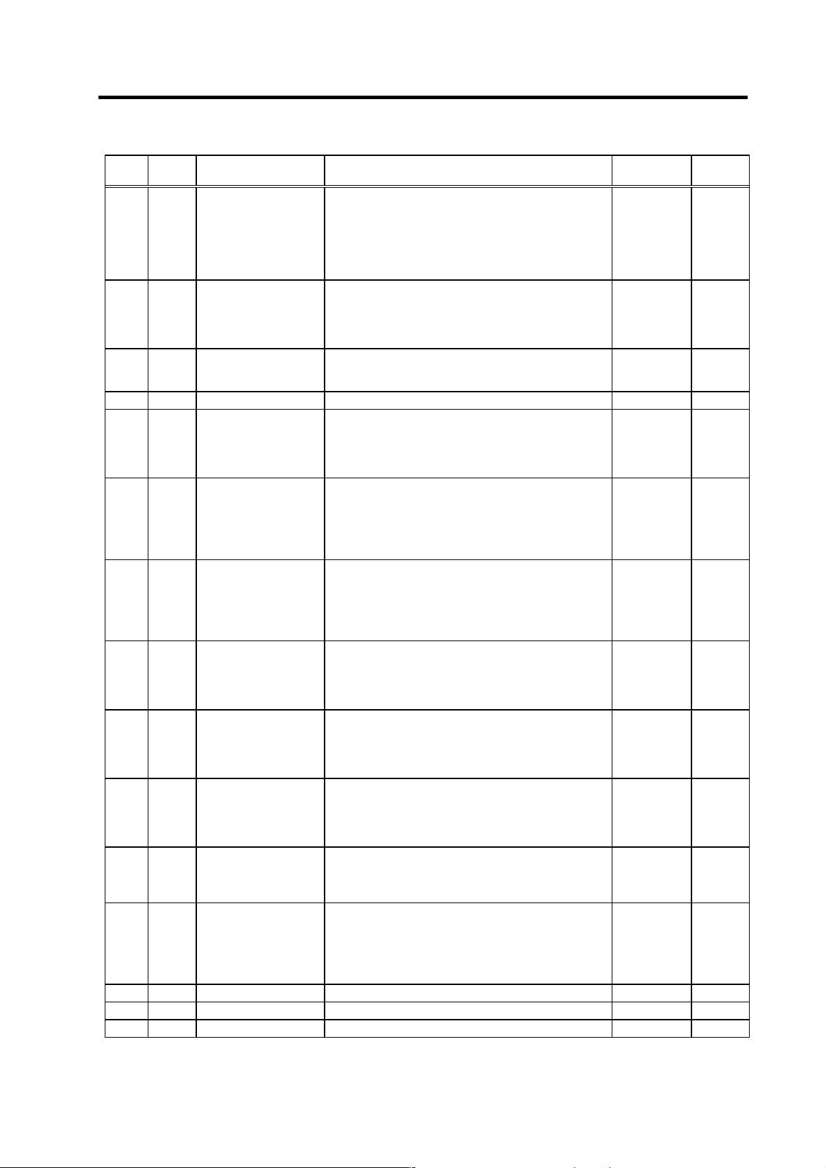
No. Abbr. Parameter name Details
Setting range
(Unit)
Standard
setting
SP114 OPER*
Orientation control
pulse miss check value
An alarm "5C" will occur if the pulse miss value at the
orientation stop exceeds this setting value. (Note that this
is invalid when set to "0".)
In this parameter, set the value to fulfill the following
conditions.
SP114 setting value > 1.5 × SP004
(orientation in-position width)
0 to 32767
(360 deg/4096)
0
SP115 OSP2*
Orientation control
speed clamp value 2
When the orientation clamp speed is changed by the
control input, this parameter setting will be used instead of
SP005: OSP.
Indexing speed clamp valid
This parameter is used when (SP097: SPEC0/bit4 = 1).
0 to 32767
(r/min)
0
SP116 OPYVR*
Minimum excitation value
after changeover (2nd
minimum excitation rate)
Set the minimum excitation rate when position control
input or external input is selected. 0 to 100 (%) 0
SP117 ORUT* Fixed control constant Set by Mitsubishi. Set "0" unless designated in particular. 0 0
SP118 ORCT*
Orientation control
number of retry times
Set the number of times to retry when an orientation or
feedback error occurs.
The warning (A9) is issued while retrying orientation, and
an alarm (5C) is issued when the set number of times is
exceeded.
0 to 100
(time)
0
SP119 MPGH*
Orientation control
position loop gain H coil
magnification
Set the compensation magnification of the orientation
position loop gain for the H coil.
H coil orientation position loop gain
= SP001 (or SP002) × SP119/256
When set to "0", will become the same as SP001 or
SP002.
0 to 2560
(1/256-fold)
0
SP120 MPGL*
Orientation control
position loop gain L coil
magnification
Set the compensation magnification of the orientation
position loop gain for the L coil.
L coil orientation position loop gain
= SP001 (or SP002) × SP120/256
When set to "0", will become the same as SP001 or
SP002.
0 to 2560
(1/256-fold)
0
SP121 MPCSH*
Orientation deceleration
rate H coil magnification
Set the compensation magnification of the orientation
deceleration rate for the H coil.
Orientation deceleration rate for the H coil
= SP006 × SP121/256
When set to "0", will become the same as SP006.
0 to 2560
(1/256-fold)
0
SP122 MPCSL*
Orientation deceleration
rate L coil magnification
Set the compensation magnification of the orientation
deceleration rate for the L coil.
Orientation deceleration rate for the L coil
= SP006 × SP122/256
When set to "0", will become the same as SP006.
0 to 2560
(1/256-fold)
0
SP123 MGD0*
Magnetic sensor output
peak value
This parameter is used for adjusting the operation during
magnetic sensor orientation. Set the peak value of the
magnetic sensor output. If the gap between the sensor
and magnet is small, set a large value. If the gap is large,
set a small value.
1 to 10000
Standard
magnet=542
Compact
magnet=500
SP124 MGD1*
Magnetic sensor linear
zone width
This parameter is used for adjusting the operation during
magnetic sensor orientation. Set the width of the magnetic
sensor linear zone. If the installation radius of the magnet
is large, set a small value.
1 to 10000
Standard
magnet=768
Compact
magnet=440
SP125 MGD2*
Magnetic sensor
changeover point
This parameter is used for adjusting the operation during
magnetic sensor orientation. Set the distance from the
target stop point for changing the position feedback to
magnetic sensor output.
Normally, a value that is approx. half of SP124 (MGDI) is
set.
1 to 10000
Standard
magnet=384
Compact
magnet=220
SP126 Not used. Set "0". 0 0
SP127 Not used. Set "0". 0 0
SP128 Not used. Set "0". 0 0
Parameters having an abbreviation with "*" (OPER *, etc.) are validated right after the settings are changed by the personal
computer, without turning the spindle drive unit's power ON and OFF.