MDS-C1-SPA Series INSTRUCTION MANUALib1500152(eng)a.pdf - 第169页
4. Spindle Adjustment 4 - 78 (5) Related parameters The parameters related to the coil changeover an d the standard setting values used when using a coil changeover motor are sho w n below. No. Abbrev . Parameter name De…
4. Spindle Adjustment
4 - 77
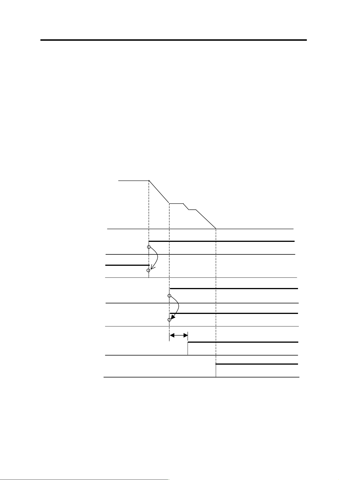
(1) Operation during orientation
[1] If the orientation command (ORC) is turned ON during spindle operation, orientation will be
completed with t he currently selected coil. (Same as conventional mechanical gears.)
[2] If orientation is to be carried out with the low-speed coil even when operating with the
high-speed coil as a means to increase the servo rigidity during orientation, use the following
procedure to orient with the low-speed coil without stopping the motor once from the
high-speed coil state.
(i) First turn the start signal (SRN o r SRI) OFF and decelerate the motor.
(ii) Using the speed detection sig nal (SD), change the L coil selection command signal (LCS)
from the high-speed coil to the low-spe ed coil.
(iii) After the TM or longer timing, or after the coil selected signal is turned ON and OFF, the
orientation command (ORC) is turned ON. Refer to the section (2)-3) for details on TM.
<Changing to the low-speed coil and orienting during operation with high-speed coil>
ON
ON
ON
ON
ON
T
M
Motor rotation speed
NC side orientation command
(Ex. M19)
Start signal
(SRN or SRI)
Speed detection signal
(SD)
L coil selection command signal
(LCS)
Orientation command signal
(ORC)
ON
Orientation complete signal
(ORCA)
4. Spindle Adjustment
4 - 78
(5) Related parameters
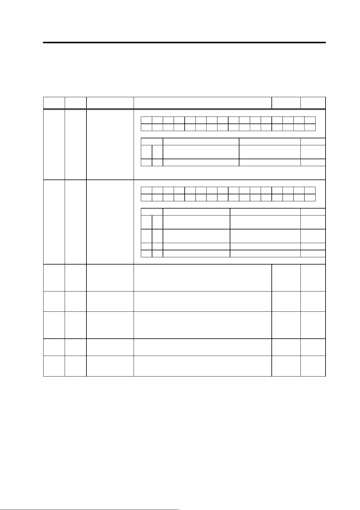
The parameters related to the coil changeover and the standard setting values used when using a
coil changeover motor are shown below.
No. Abbrev. Parameter name Description
Setting
range
Standard
value
SP037 SFNC5 Spindle function 5
F E D C B A 9 8 7 6 5 4 3 2 1 0
mkc2 mkch invm mtsl
bit Meaning when "0" is set Meaning when "1" is set Standard
0 mtsl1 Special motor constant setting invalid S pecial motor constant se tting
valid
1
2 mkch Coil switch function invalid Coil switch function valid 1
Set to "0003" when using coil changeover motor.
SP038 SFNC6 Spindle function 6
F E D C B A 9 8 7 6 5 4 3 2 1 0
lbsd hbsd lwid hwid
bit Meaning when "0" is set Meaning when "1" is set Standard
0
hwid H-coil wide-range constant output
invalid
H-coil wide-range constant output
valid
0
1
lwid L-coil wide-range constant output
invalid
L-coil wide-range constant output
valid
0
2 hbsd H-coil base slide invalid H-coil base slide valid 0
3 lbsd L-coil base slide invalid L-coil base slide valid 0
SP020 SDTS*
Speed detection
set value
Set the motor speed for which speed detection output is
performed.
The setting value is determined by Mitsubishi according to the
specifications of coil changeover motor.
0 to 32767
(r/min)
Depends
on the
motor to be
used.
SP047 SDTR* Speed detection
reset value
Set the reset hysteresis width for a speed detection set value
defined in SP020 (SDTS).
0 to 1000
(r/min)
Lathe: 300
Machining:
100
SP059 MKT
Winding
changeover base
shut-off timer
Set the base shut-off time for contactor switching at coil
changeover.
Note that the contactor may be damaged with burning if the
value of this parameter is too small.
50 to 10000
(ms)
150
SP060 MKT2
Current limit timer
after coil
changeover
Set the current limit time to be taken after completion of
contactor switching at winding changeover.
0 to 10000
(ms)
500
SP061 MKIL
Current limit value
after winding
changeover
Set the current limit value during a period defined in SP060
(MKT2) after completion of contactor switching at winding
changeover.
0 to 120
(%)
75

4. Spindle Adjustment
4 - 79
No. Abbrev. Parameter name Description
Setting
range
Standard
value
SP129
to
SP140
HI01
to
HI12
General-purpose input
selection
Set the general-purpose input signals IN1 to IN12 as to which
function they should have. To have the coil changeover function,
set "18" (L coil selection command) in one of those signals.
0 to 21 -
SP141
to
SP154
HO1e
to
HO1c
General-purpose
output selection
Set the general-purpose output signals OUT1 to OUT8 (open
emitter) or OUT1C to OUT6C (open collector) as to which
function they should have. Set "18" (L coil selected signal) in
one of those signals. Also, set "16" (changing coil) in another
signal as required.
0 to 23 -
SP257
to
SP320
Motor constant (H coil)
These parameters are valid only in the following two conditional
cases.
(a) SP034(SFNC2)/bit0=1 and SP034(SFNC2)/bit2=0
Set the motor constants for the special and non-coil
changeover motor not indicated in the explanation of SP040
(MTYP).
(b) SP034(SFNC2)/bit0=1 and SP034(SFNC2)/bit2=1
Set the H coil side motor constants of the coil changeover
motor.
(Note) It is not allowed for the user to change the setting.
(HEX setting)
0000 to
FFFF
0000
SP321
to
SP384
Motor constant (L coil)
These parameters are valid only in the following case.
(a) SP034(SFNC2)/bit0=1 and SP034(SFNC2)/bit2=1
Set the L coil side motor constants of the coil changeover
motor.
(Note) It is not allowed for the user to change the setting.
(HEX setting)
0000 to
FFFF
0000