MDS-C1-SPA Series INSTRUCTION MANUALib1500152(eng)a.pdf - 第192页
5. Troubleshooting 5 - 21 5-3-3 Troubleshooting for each warning No. W arning No. A9 Orientation feedback error warning Retrying during an orientation feedback error . Investigation details Investigation results Remedies…
5. Troubleshooting
5 - 20
Alarm No.
8D
Detection converter unit 2, CPU error
With the servo, a CPU error was detected with the MDS-B-HR unit. With the spindle, a CPU
error was detected with the MDS-B-PJEX unit.
Investigation details Investigation results Remedies
No abnormality is found in particular. Replace the detection converter unit.1 Check if there is any abnormality in
the detector's ambient environment.
(Ex. Ambient temperature, noise,
grounding)
An abnormality was found in the
ambient environment.
Take remedies according to the
causes of the abnormality.
Ex. High temperature:
Check the cooling fan.
Incomplete grounding:
Additionally ground.
Alarm No.
8E
Detection converter unit 2, data error
A data error was detected with the MDS-B-HR unit.
Investigation details Investigation results Remedies
The cable is broken. Replace the cable. 1 Check whether the cable between
the linear scale and MDS-B-HR is
broken.
The cable is not broken. Investigate item 2.
No abnormality is found in particular. Investigate item 3. 2 Check if there is any abnormality in
the unit's ambient environment.
(Ex. Ambient temperature, noise,
grounding)
An abnormality was found in the
ambient environment.
Take remedies according to the
causes of the abnormality.
Ex. High temperature:
Check the cooling fan.
Incomplete grounding:
Additionally ground.
The state is improved. Replace the MDS-B-HR unit. 3 Try replacing the MDS-B-HR unit.
The state is not improved. Replace the linear scale.
5. Troubleshooting
5 - 21
5-3-3 Troubleshooting for each warning No.
Warning No.
A9
Orientation feedback error warning
Retrying during an orientation feedback error.
Investigation details Investigation results Remedies
1 Check the alarm No. "5C" items.
Warning No.
E1
Overload warning
The overload detection level is 80% or more.
Investigation details Investigation results Remedies
1 Check the alarm No. "50" items.
Warning No.
E4
Parameter error warning
A parameter exceeding the setting range was set.
Investigation details Investigation results Remedies
1 Check the error parameter No. SV001 to SV065
(M60S system: 2201 to 2265)
SP001 to SP384
(M60S system: 3201 to 3584)
Set the value within the designated
setting range.
Warning No.
E7
NC emergency stop
Emergency stop was input from the NC.
Investigation details Investigation results Remedies
Emergency stop was input. The NC is in the emergency stop
state. (Normal)
1 Check whether NC emergency stop
was input.
Emergency stop was not input. Investigate item 2.
An alarm is occurring in another drive
unit.
Reset the alarm in the other drive
unit.
2 Check whether an alarm is occurring
in another drive unit.
An alarm is not occurring. Investigate item 3.
The terminator or battery unit's cable
is disconnected.
Correctly connect. 3 Check the NC communication bus
line.
The NC communication bus
connector (CN1A, CN1B) is loose, or
the cable is broken.
Correctly connect the cable.
Warning No.
E9
Instantaneous power failure warning
An instantaneous power failure occurred.
Investigation details Investigation results Remedies
1 Check the alarm No. "71" items.
Warning No.
EA
External emergency stop
The external emergency stop signal was input.
Investigation details Investigation results Remedies
Use not allowed. Invalidate the external emergency
stop.
1 Check whether the specifications
allow use of the external emergency
stop.
Use is allowed. Investigate item 2.
24V is input. Replace the power supply unit. 2 Measure the input voltage of the
CN23 connector. (While emergency
stop is cancelled.)
24V is not input. Check whether the external
emergency stop cable is broken, or
check the external contact operation.
Warning No.
EB
Over-regeneration warning
The over-regeneration level is 80% or more.
Investigation details Investigation results Remedies
1 Check the alarm No. "73" items.
5. Troubleshooting
5 - 22
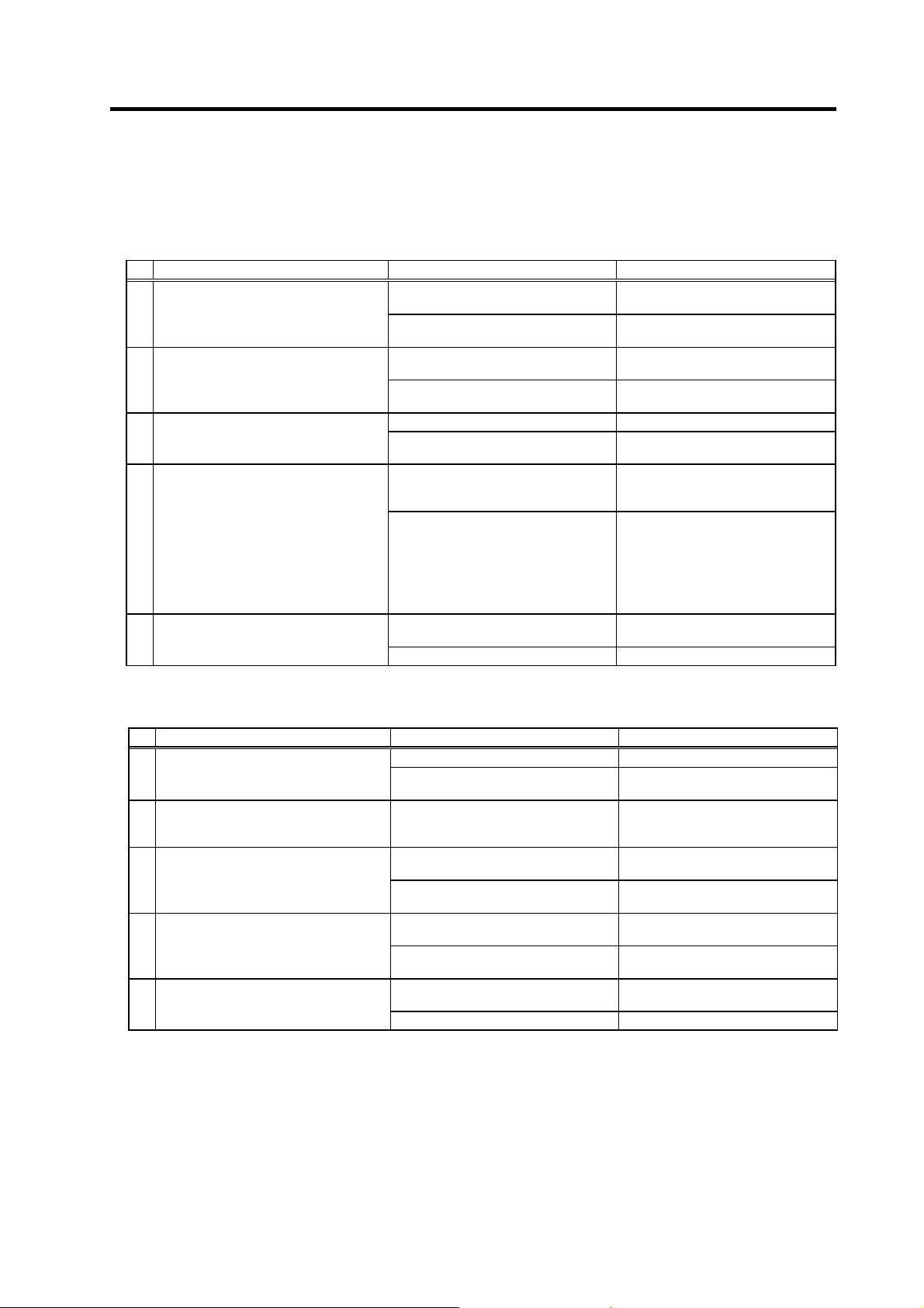
5-3-4 Troubleshooting the spindle system when there is no alarm or warning
If an abnormality is observed in the spindle system but no alarm or warning has occurred, refer to the
following table and check the state.
[1] No abnormality is displayed, but the motor does not rotate.
Investigation item Investigation results Remedies
The wiring is incorrect, the screws are
loose, or the cables are disconnected.
Correctly wire. Correctly tighten the
screws. Replace the cables.
1
Check the wiring around the spindle drive
unit.
Also check for loosening in the terminal
screws and disconnec- tions, etc.
No particular problems found.
Investigate investigation item 2 and
remedy.
The voltage is exceeding the
specification value.
Restore the power to the correct state.
2 Check the input voltage.
The voltage is within the specification
value.
Investigate investigation item 3 and
remedy.
The correct values are not set. Set the correct values.
3 Check all of the spindle parameters.
The correct values are set.
Investigate investigation item 4 and
remedy.
The signals are not input or the
sequence is incorrect.
The orientation command is input.
Correct the input signals.
4
Check the input signals.
• Are the READY, forward run and
reverse run signals input?
• In particular, the forward run and
reverse run signals must be input at
least one second after READY is
turned ON.
• Check whether the forward run and
reverse run signals are turned ON
simultaneously.
No particular problems found.
Investigate investigation item 5 and
remedy.
The speed command is not input
correctly.
Input the correct speed command.
5 Check the speed command.
The speed command is input correctly. Replace the unit.
[2] No fault is displayed, but the motor only rotates slowly, or a large noise is heard from the
motor.
Investigation item Investigation results Remedies
The wires are not connected correctly. Correctly connect.
1
Check the U, V and W wiring between the
spindle drive unit and motor.
The wires are connected correctly.
Investigate investigation item 2 and
remedy.
2 Check the input voltage.
One of the three phases is not within the
specification value.
No particular problems found.
Restore the power to the correct state.
Investigate investigation item 3 and
remedy.
The speed command is not input
correctly.
Check the NC and PLC sequence.
3 Check the speed command.
The speed command is input correctly.
Investigate investigation item 4 and
remedy.
The connector is disconnected (or
loose).
Correctly connect the connector.
4
Tug on the connector by hand to check
whether the speed detector connector
(drive unit side and speed detector side)
is loose.
The connector is not disconnected (or
loose).
Investigate investigation item 5 and
remedy.
The connection is faulty or disconnected.
Replace the detector cable.
Correct the connection.
5
Turn the power OFF, and check the
connection of the speed detector cable
with a tester.
The connection is normal. Replace the drive unit.