MDS-C1-SPA Series INSTRUCTION MANUALib1500152(eng)a.pdf - 第38页
2. Wiring and Connection 2 - 10 (2) Control circuit connector Unit Terminal MDS-C1-SPA-55 to 300 Connector position [1] CN11 [2] CN12 [3] CN9A [4] CN4 [5] CN5 [6] CN6 [7] CN10 [8] CN8A [5] CN5 [6] CN6 [9] CN8A [3] CN9A […
2. Wiring and Connection
2 - 9
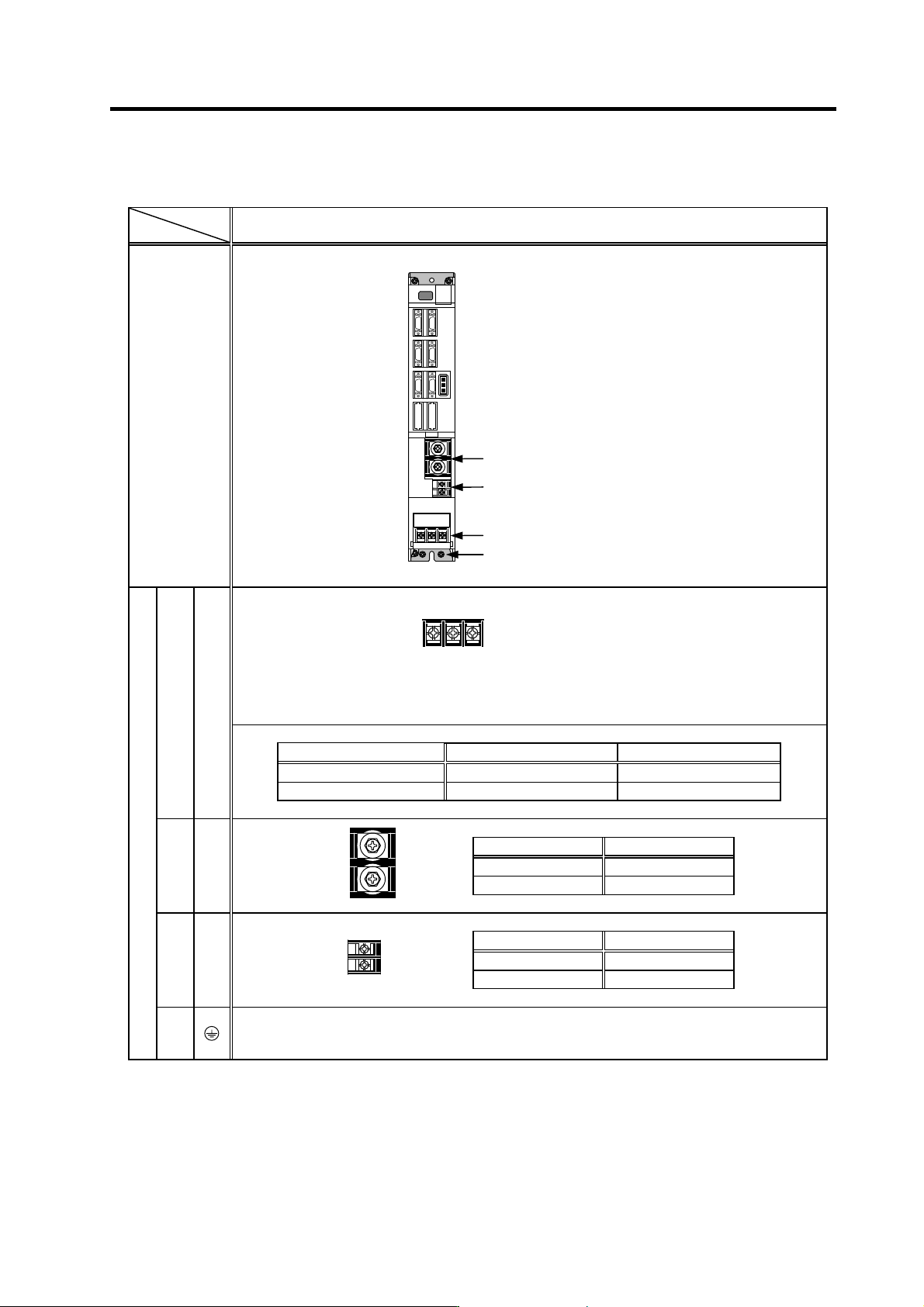
Spindle drive unit
Unit
Terminal
MDS-C1-SPA-55 to 300
Terminal
position
MDS-C1-SPA- 55 to 185 220 to 300
Screw size M5 M8
Tightening torque 3.2Nm 13.2Nm
[1] TE1
Compatible unit All capacity
Screw size M6
Tightening torque 5.0Nm
[2] TE2
Compatible unit All capacity
Screw size M4
Tightening torque 2.0Nm
[3] TE3
Terminal specification/Pin assignment
[4]
The PE screw size is the same as TE1.
L+
L-
L11
L21
[
2
]
[
3
]
[1]
[4]
U V W
2. Wiring and Connection
2 - 10
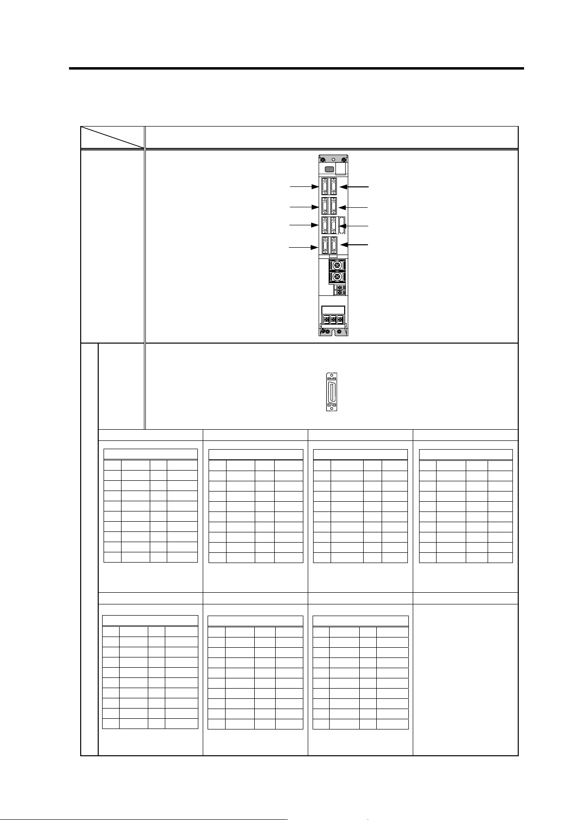
(2) Control circuit connector
Unit
Terminal
MDS-C1-SPA-55 to 300
Connector
position
[1] CN11
[2] CN12
[3] CN9A
[4] CN4
[5] CN5
[6] CN6
[7] CN10
[8] CN8A
[5] CN5 [6] CN6 [9] CN8A [3] CN9A
[7] CN10 [1] CN11 [2] CN12
Connector specifications
[1]
[3]
[5]
[2]
[4]
[9]
[6]
[7]
Pi
n
N
o.
N
o.
1
No.10
N
o.
1
1
No.20
Pin assignment
1 GND 11 GND
2 RD 12 RD*
3 MOH 13 RG
4 SD 14 SD*
5 P15 15 N15
6 PA 16 RA
7 PB 17 RB
8 PZ 18 -
9 P24 19 -
10 - 20 -
Pin assignment
1 GND 11 GND
2 MA 12 MA*
3 MB 13 MB*
4 MZ 14 MZ*
5 P15B 15 GND
6 MSA 16 MSC
7 LSA 17 LSC
8 - 18 -
9 - 19 P5
10 P5 20 P5
Pin assignment
1 GND 11 GND
2 SYA 12 SYA*
3 SYB 13 SYB*
4SYZ 14SYZ*
5 SES 15 ORS
6RP 16OR3
7 SE1 17 OR2
8 SE2 18 OR1
9- 19-
10 - 20 -
Pin assignment
1 GND 11 GND
2 DR 12 DX
3 CLK 13 FSX
4 P5 14 -
5 RX 15 TX
6 - 16 -
7 IU 17 IV
8 OUT8 18 P5
9 SM0 19 LM0
10 - 20 -
Pin assignment
1 REDY 11 SRN
2 SRI 12 IN1
3 IN2 13 IN3
4 IN4 14 IN5
5 IN6 15 IN7
6 IN8 16 IN9
7 - 17 +24V
8 IN10 18 IN11
9 IN12 19 CES1
10 RG 20 OUT6C
Pin assignment
1 1H 11 2H
2 3H 12 4H
3 5H 13 6H
4 7H 14 8H
5 9H 15 10H
6 11H 16 12H
7 OUT1 17 OUT2
8 OUT3 18 OUT4
9 OUT5 19 CES3
10 OUT6 20 OUT7
Pin assignment
1 R1 11 R2
2 R3 12 R4
3 R5 13 R6
4 R7 14 R8
5 R9 15 R10
6 R11 16 R12
7 OUT1C 17 OUT2C
8 OUT3C 18 OUT4C
9 OUT5C 19 CES2
10 FA 20 FC
2. Wiring and Connection
2 - 11
2-3 Drive unit connection
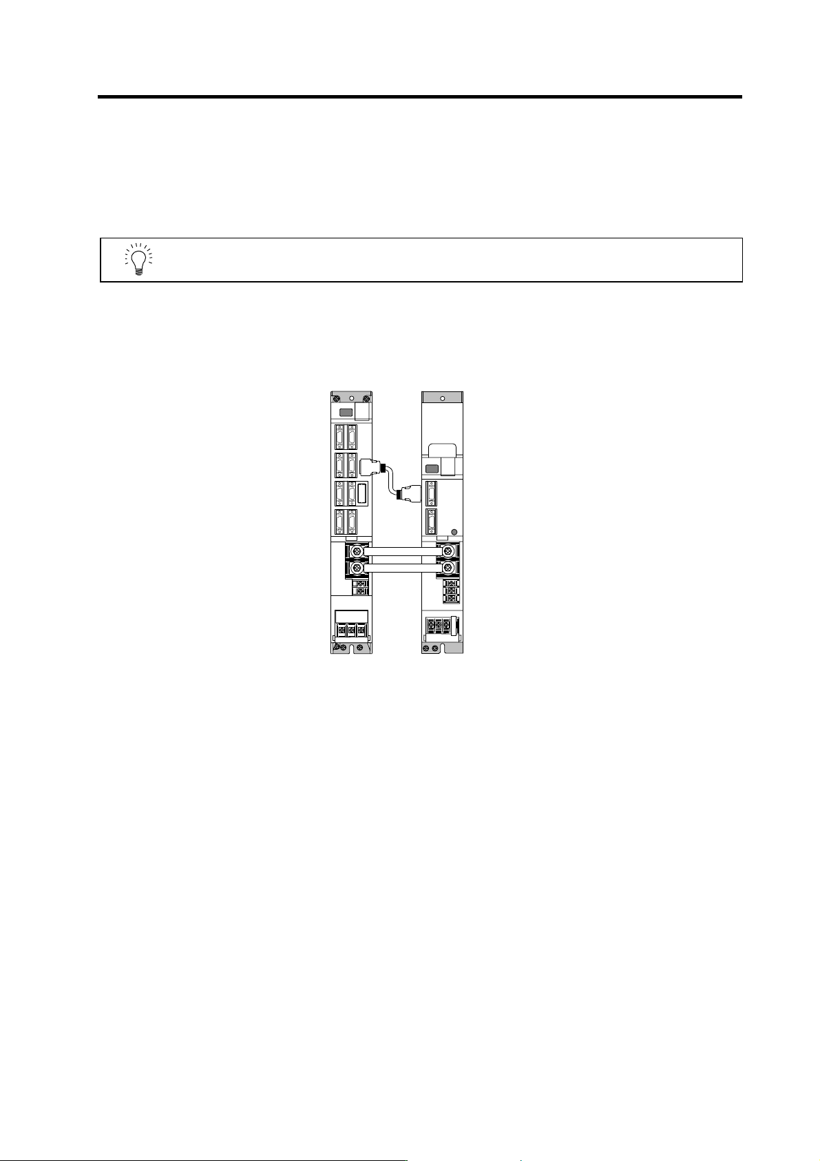
In this section, the connection between the spindle drive unit and power supply unit is shown. There is
space between units in the following diagram to make clearly understandable. However, actually, install
the drive units so that the space between the drive units is within 3cm.
POINT
Even if two or more spindle drive units are used, keep the setting of the spindle
drive unit’s rotary switch to “0”. This switch has no relation to the axis No.
(1) When using one power supply unit for one spindle drive unit
MDS-C1-SPA MDS-C1-CV
CN4
CN4
Connection when using one power supply unit