MDS-C1-SPA Series INSTRUCTION MANUALib1500152(eng)a.pdf - 第81页
3. Setup 3 - 21 No. Abbr. Parameter name Details Setting range Standard SP149 HO1c General-purpose output selection Open collector 1 Assign signals to general-purpose output (open collector) 1(OUT1c: CN12-7 pin). The set…
3. Setup
3 - 20
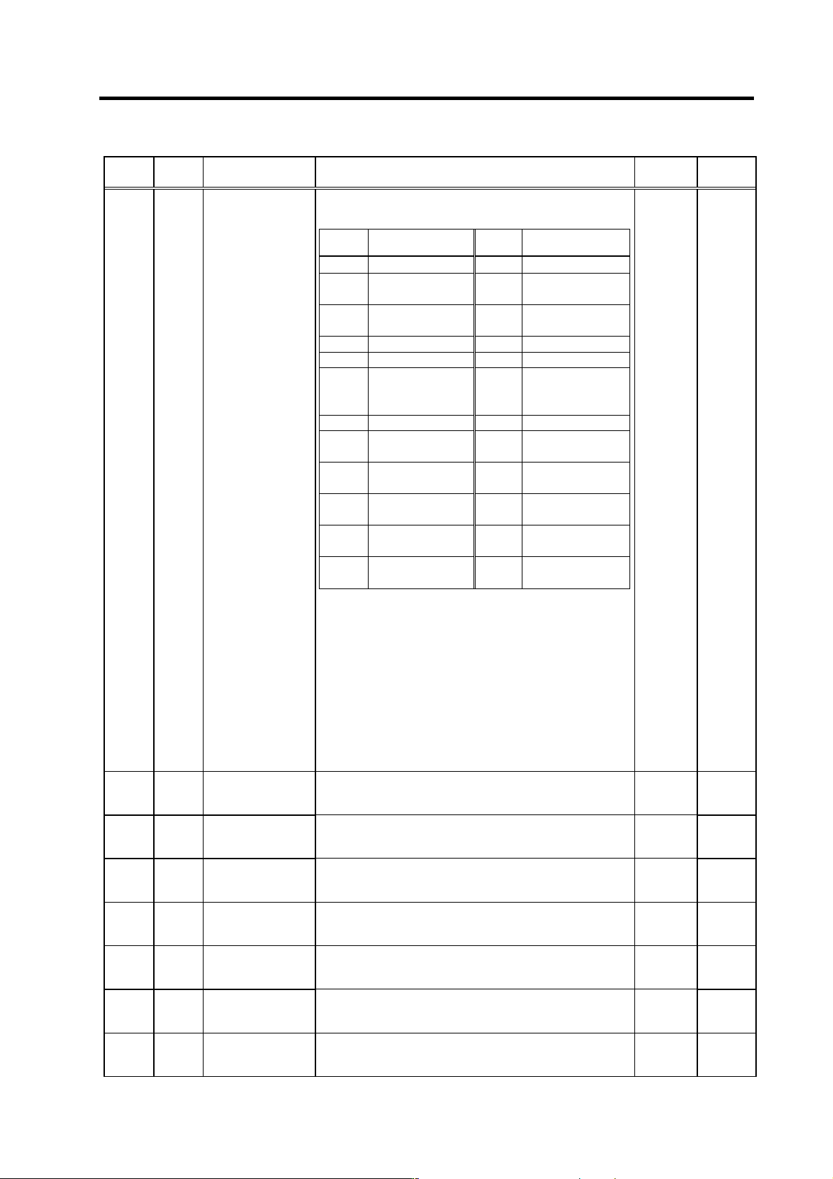
No. Abbr. Parameter name Details
Setting
range
Standard
SP141 HO1e
General-purpose
output selection
Open emitter 1
Assign signals to general-purpose output (open emitter) 1
(OUT1: CN11-7 pin). Select the signal to be assigned from the
table below.
Setting
value
Meaning
Setting
value
Meaning
0 Not used for output 12 Current detection
1 Orientation
complete
13 Speed detection
2 Positioning
complete
14 Up-to-speed
3 Torque reach 15
Zero speed
4 In torque limit 16
Changing coil
5
Setting prohibited
17 In 1-drive unit
2-motor
changeover
6
Setting prohibited
18 L coil selected
7
Motor in forward
run
19 In sub-motor
selection
8
Motor in reverse
run
20 Alarm code output
1
9 In alarm 21 Alarm code output
2
10 In emergency stop 22 Alarm code output
3
11 In ready ON 23 Alarm code output
4
(Note 1) Do not set "5" or "6" in any one of the parameters from
SP141(HO1e) to SP154(HO6c).
(Note 2) Always set to "0" for any unused input among the
parameters from SP141(HO1e) to SP154(HO6c).
(Note 3) When handling the parameters from SP141(HO1e) to
SP148(HO8c) in one group and the parameters from
SP149(HO1c) to SP154(HO6c) in another group, do
not set any duplicated value within the same group
(except for "0"). If groups are different, the same value
can be set.
(Note 4) When selecting the alarm code output, always set all of
the alarm code outputs (1 to 4) to any of the
parameters from SP141(HO1e) to SP154(HO6c).
0 to 23 0
SP142 HO2e
General-purpose
output selection
Open emitter 2
Assign signals to general-purpose output (open emitter)
2(OUT2: CN11-17 pin).
The setting method is the same as SP141(HO1e).
0 to 23 0
SP143 HO3e
General-purpose
output selection
Open emitter 3
Assign signals to general-purpose output (open emitter)
3(OUT3: CN11-8 pin).
The setting method is the same as SP141(HO1e).
0 to 23 0
SP144 HO4e
General-purpose
output selection
Open emitter 4
Assign signals to general-purpose output (open emitter)
4(OUT4: CN11-18 pin).
The setting method is the same as SP141(HO1e).
0 to 23 0
SP145 HO5e
General-purpose
output selection
Open emitter 5
Assign signals to general-purpose output (open emitter)
5(OUT5: CN11-9 pin).
The setting method is the same as SP141(HO1e).
0 to 23 0
SP146 HO6e
General-purpose
output selection
Open emitter 6
Assign signals to general-purpose output (open emitter)
6(OUT6: CN11-10 pin).
The setting method is the same as SP141(HO1e).
0 to 23 0
SP147 HO7e
General-purpose
output selection
Open emitter 7
Assign signals to general-purpose output (open emitter)
7(OUT7: CN11-20 pin).
The setting method is the same as SP141(HO1e).
0 to 23 0
SP148 HO8e
General-purpose
output selection
Open emitter 8
Assign signals to general-purpose output (open emitter)
8(OUT8: CN9A-8 pin).
The setting method is the same as SP141(HO1e).
0 to 23 0
3. Setup
3 - 21
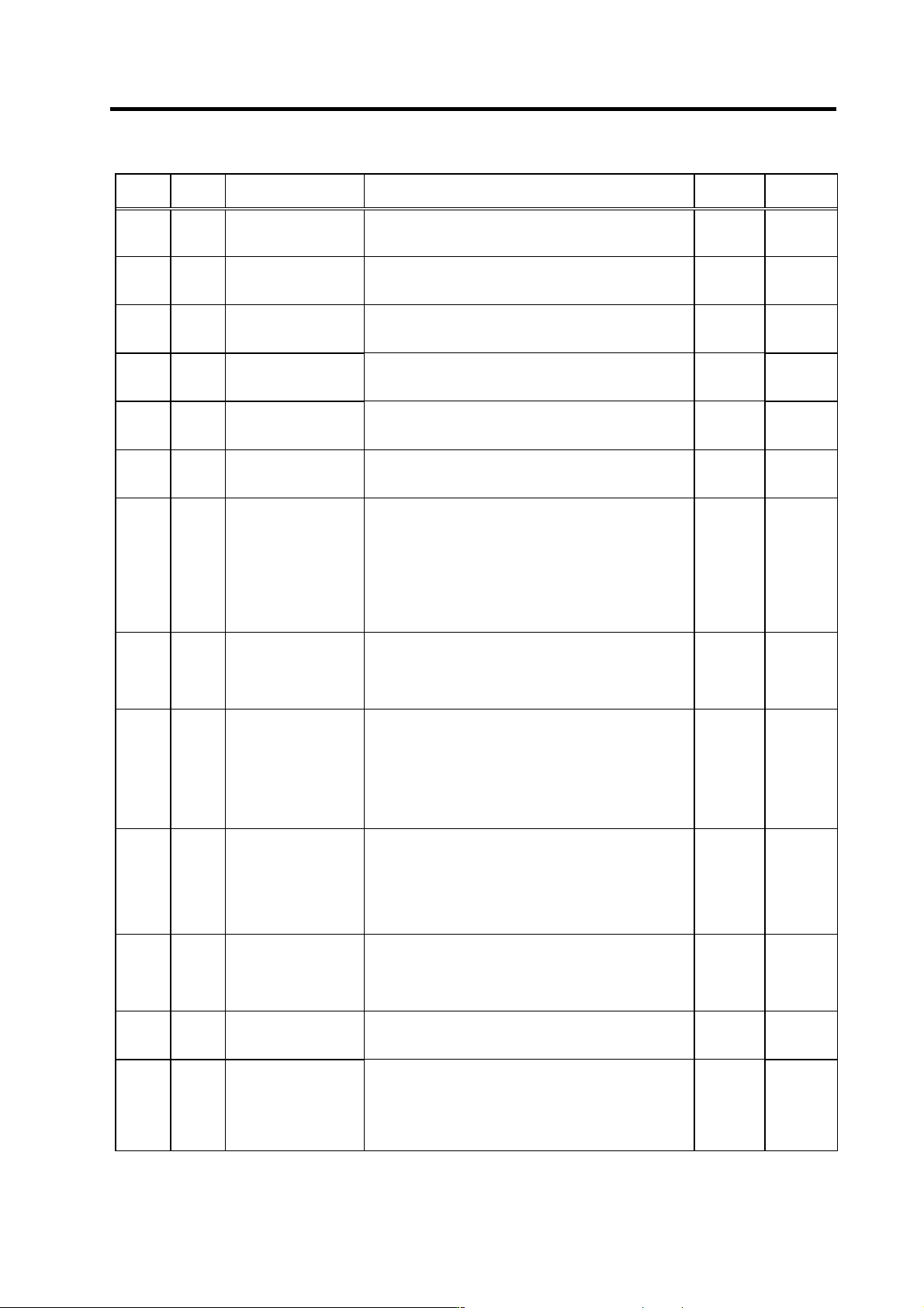
No. Abbr. Parameter name Details
Setting
range
Standard
SP149 HO1c
General-purpose output
selection
Open collector 1
Assign signals to general-purpose output (open collector)
1(OUT1c: CN12-7 pin).
The setting method is the same as SP141(HO1e).
0 to 23 0
SP150 HO2c
General-purpose output
selection
Open collector 2
Assign signals to general-purpose output (open collector)
2(OUT2c: CN12-17 pin).
The setting method is the same as SP141(HO1e).
0 to 23 0
SP151 HO3c
General-purpose output
selection
Open collector 3
Assign signals to general-purpose output (open collector)
3(OUT3c: CN12-8 pin).
The setting method is the same as SP141(HO1e).
0 to 23 0
SP152 HO4c
General-purpose output
selection
Open collector 4
Assign signals to general-purpose output (open collector)
4(OUT4c: CN12-18 pin).
The setting method is the same as SP141(HO1e).
0 to 23 0
SP153 HO5c
General-purpose output
selection
Open collector 5
Assign signals to general-purpose output (open collector)
5(OUT5c: CN12-9 pin).
The setting method is the same as SP141(HO1e).
0 to 23 0
SP154
HO6c
General-purpose output
selection
Open collector 6
Assign signals to general-purpose output (open collector)
6(OUT6c: CN10-20 pin).
The setting method is the same as SP141(HO1e).
0 to 23 0
SP155 SAtyp
S analog speed
command input type
Select where to input the S analog input.
[0]: Input between SE1(CN8A-7 pin) and SE2(CN8A-8 pin)
(Standard)
(Bipolar input: Possible to input 0 to ±10V)
[1]: Input between OR2(CN8A-17 pin) and SE1(CN8A-18
pin)
(Unipolar input: Possible to input 0 to +10V only)
Note that when "1" is set, the over writing function cannot
be used.
0 to 1
0
SP156 DGtyp
Digital speed command
input type
Set the digital speed command input method.
"0": Signed binary
"1": No sign 12-bit binary
"2": BCD2 digits
"3": BCD3 digits
0 to 3 0
SP157 SAavr
S analog speed
command input filter
Set the filter time constant of the S analog speed command
input. The actual time in respect to setting value is as
follows.
Filter time constant = 0.8ms × setting value
When "0" is set, this becomes 25.6ms.
Use the standard setting value if there is no problem.
Note that this setting is invalid during S analog high-speed
tapping.
0 to 32767
(0.8ms)
0
SP158 Adofs*
S analog speed
command input offset
Set the offset value of the S analog speed command input.
Set the value so that the spindle almost stops when the
input command is "0".
Note that the rotation of the spindle motor may not be
stopped in full with this setting.
This setting fluctuates depending on the usage time and
ambient temperature.
-999 to 999
When
SP155=0:
0
When
SP155=1:
262
SP159 ADcp1*
S analog speed
command input clamp 1
Set the + side non-sensitive band of the S analog speed
command input.
The speed command input is not accepted when the input
command is lower than the value set here. Thus, the motor
remains stopped
0 to 999 0
SP160 ADcp2*
S analog speed
command input clamp 2
Set the - side non-sensitive band of the S analog speed
command input.
The detail is the same as SP159; only set in the minus side.
-999 to 0 0
SP161 Sgain*
S analog speed
command input gain
Set the gain of the S analog speed command input. Set so
that the motor runs at the highest speed when the
maximum speed command is input.
0 to 2500
(1/
1000-fold)
When
SP155=0:
1053
When
SP155=1:
1147
Parameters having an abbreviation with "*" (Adofs*, etc.) are validated right after the settings are changed by the personal
computer, without turning the spindle drive unit's power ON and OFF.
3. Setup
3 - 22
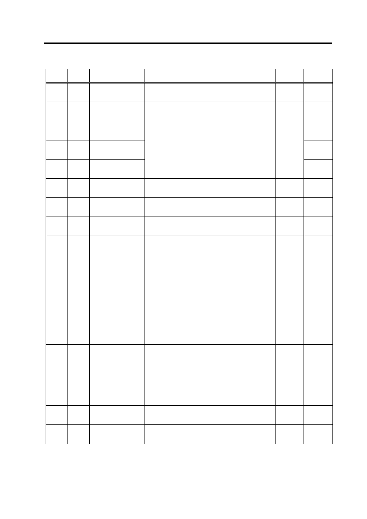
No. Abbr. Parameter name Details
Setting
range
Standard
SP162 SS00 Speed setting 0
Regardless of whether the speed command mode is analog
or digital, the motor is run by the value set here when the
forward/reverse run signal is input.
0 to 32767
(r/min)
0
SP163 SS01 Speed setting 1
Set the motor speed command value when the speed
selection 1 is assigned to the general-purpose input and the
input is turned ON.
0 to 32767
(r/min)
0
SP164 SS02 Speed setting 2
Set the motor speed command value when the speed
selection 1,2 or 1,2,3 are assigned to the general-purpose
input and only the speed selection 2 is turned ON.
0 to 32767
(r/min)
0
SP165 SS03 Speed setting 3
Set the motor speed command value when the speed
selection 1,2 or 1,2,3 are assigned to the general-purpose
input and the speed selection 1,2 are turned ON.
0 to 32767
(r/min)
0
SP166 SS04 Speed setting 4
Set the motor speed command value when the speed
selection 1,2,3 are assigned to the general-purpose input
and the speed selection 3 is turned ON.
0 to 32767
(r/min)
0
SP167 SS05 Speed setting 5
Set the motor speed command value when the speed
selection 1,2,3 are assigned to the general-purpose input
and the speed selection 1, 3 are turned ON.
0 to 32767
(r/min)
0
SP168 SS06 Speed setting 6
Set the motor speed command value when the speed
selection 1,2,3 are assigned to the general-purpose input
and the speed selection 2, 3 are turned ON.
0 to 32767
(r/min)
0
SP169 SS07 Speed setting 7
Set the motor speed command value when the speed
selection 1,2,3 are assigned to the general-purpose input
and the speed selection 1,2,3 are all turned ON.
0 to 32767
(r/min)
0
SP170 SSchg
Speed setting switch
filter
Set the filter time constant when changing the speed
selection command input. The actual time in respect to the
setting value is as follows.
Filter time constant = 0.8ms × setting value
When "0" is set, this becomes no filter.
Use the standard setting value if there is no problem.
0 to 32767
(0.8ms)
0
SP171 HSPT
S analog high-speed
tapping motor maximum
speed
Set the maximum motor speed during S analog high-speed
tapping.
The value set in SP017(TSP) is applied when "0" is set.
During S analog high-speed tapping, when the gear noise
is louder than the regular speed loop operation or when the
tapping accuracy should be improved, set the motor
maximum tapping speed here.
0 to 32767
(r/min)
0
SP172 VGHP
S analog high-speed
tapping speed loop
proportional gain
Set the speed loop proportional gain during S analog
high-speed tapping. The higher the gain becomes, the
higher the response, but the greater the vibration and noise
become.
The value set in SP022(VGNP1) is applied when "0" is set.
0 to 1000 0
SP173 VGHI
S analog high-speed
tapping speed loop
integral gain
Set the speed loop integral gain during S analog
high-speed tapping.
If the value of SP172(VGHP) is set, set the value so that the
setting value’s proportion between SP172 and SP173 is
1:1.
The value set in SP023(VGNI1) is applied when "0" is set.
0 to 1000 0
SP174 HPYV
S analog high-speed
tapping variable
excitation rate (min
value)
Set the minimum value of the variable excitation rate during
S analog high-speed tapping.
Select a smaller value when gear noise is high. Select a
bigger value to improve tapping accuracy.
0 to 100
(%)
0
SP175 HSgn*
S analog high-speed
tapping speed
command gain
Set the speed command voltage gain during S analog
high-speed tapping.
The value set in SP161(Sgain) is applied when "0" is set.
0 to 2500
(1/1000-fold
)
0
SP176 HADof*
S analog high-speed
tapping speed
command offset
Set the speed command voltage offset value during S
analog high-speed tapping.
The value set in SP158(ADofs) is applied when "0" is set.
-999 to 999 0
Parameters having an abbreviation with "*" (HSgn*, etc.) are validated right after the settings are changed by the personal
computer, without turning the spindle drive unit's power ON and OFF.