MDS-C1-SPA Series INSTRUCTION MANUALib1500152(eng)a.pdf - 第176页
5. Troubleshooting 5 - 5 Power supply alarm No. LED display Alarm name SP Alarm d etails Reset 61 Power module overcurrent § The power module's overcurrent protection function activated. PR 62 Frequency error § The …
5. Troubleshooting
5 - 4
5-2 Protective functions list of units
5-2-1 List of alarms
When an alarm occurs, the spindle drive unit will coast to a stop or will decelerate to a stop. Check the
alarm No., and remove the cause of the alarm by following this list.
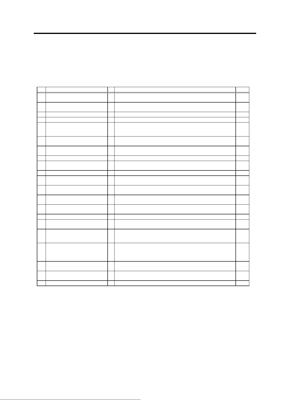
Drive unit alarm
No. Alarm name SP Alarm details Reset
12 Memory error 1
A CPU or internal memory error was detected during the self-check at
power ON.
AR
13 Software processing error 1
§
The software process was not completed within the specified time.
(CPU1)
PR
17 A/D converter error
An error was detected in the A/D converter for current FB detection. PR
20 Motor side detector, No signal 1
{
A PLG Z-phase no signal was detected. PR
21 Machine side detector, No signal 2
{
The pulse-type linear scale or ball screw side detector's ABZ-phase no
signal was detected with the servo, or the encoder no-signal was
detected with the spindle.
PR
23 Excessive speed deflection 1
§
A difference of 50r/min or more between the speed command and
speed feedback continued for longer than the set time.
PR
31 Overspeed
§
A rotation speed exceeding the motor's tolerable rotation speed was
detected.
PR
32 Power module overcurrent
§
The power module's overcurrent protection function activated. PR
37 Initial parameter error
An illegal parameter was detected in the parameters received from the
NC at NC power ON.
PR
3B Power module overheat
§
The power module's temperature protection function activated. PR
3F Speed excessive deflection 2
§
During constant speed operation, the difference between the speed
command and speed feedback exceeded the set amount and set time.
PR
40 Detector changeover unit,
changeover error
§
During 1-drive unit 2-motor control, an error was detected in the motor
changeover signal received form the detector changeover unit.
PR
41 Detector changeover unit,
communication error
§
During 1-drive unit 2-motor control, an error was detected in the
communication with the detector changeover unit.
PR
42 Feedback error 1
§
With the servo, pulse-type position detector feedback signal error was
detected. With the spindle, a PLG feedback signal error was detected.
PR
46 Motor overheat
{
The temperature protection function in the motor or detector activated. NR
50 Overload 1
§
The overload detection level reached 100% or more. The motor or drive
unit is in the overload state.
NR
51 Overload 2
§
With the servo, a current command exceeding 95% of the unit's
maximum current continued for one second or more. With the spindle, a
load exceeding the continuous rating continued for 30 minutes or more.
NR
52 Excessive error 1
{
With the servo, the difference of the motor's actual position at servo ON
and the theoretical position exceeded the setting value. With the
spindle, the difference of the position command and position feedback
exceeded the setting value.
NR
57 Option error
An input that does not exist in the option settings was selected for the
general-purpose input.
5C Orientation feedback error
§
After orientation was completed, the command and feedback error
exceeded the parameter setting.
PR
88 Watchdog
§
The system does not operate correctly.
(Note 1) Motor stopping method applied when spindle drive unit alarm occurs is indicated in the column of SP.
(Note 2) Spindle (SP) alarm stopping method
{: Deceleration control (when SP038/bit0=1 is set) , Coast to a stop (when SP038/bit0=0 is set).
§: Coast to a stop
: Initial error (while motor is stopped)
Resetting methods
PR: Reset by setting the alarm reset signal to the general-purpose input of the spindle drive unit and turning the signal ON/OFF.
This alarm can also be reset with the AR resetting conditions.
AR: Reset by turning the spindle drive unit power ON again.
5. Troubleshooting
5 - 5
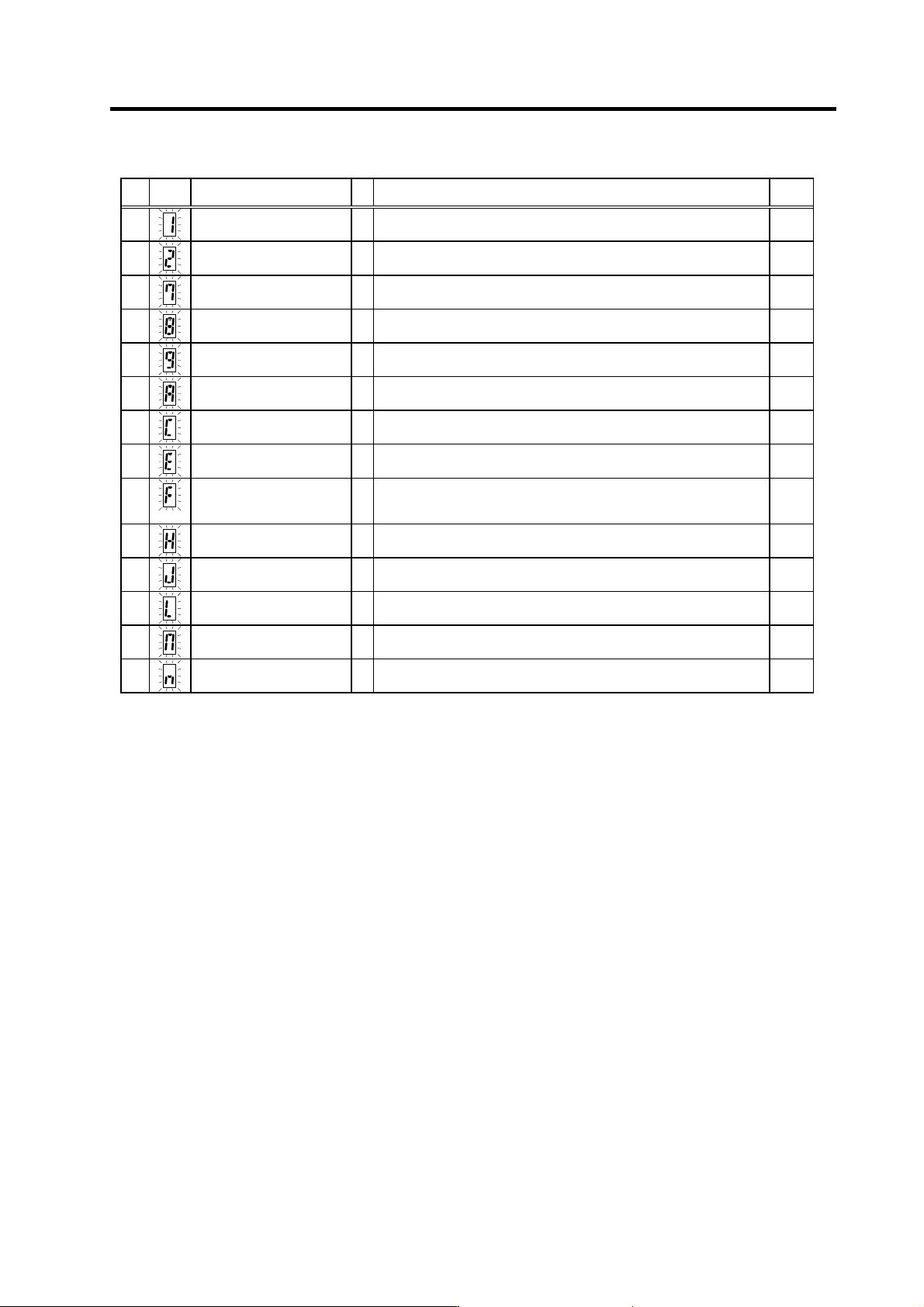
Power supply alarm
No.
LED
display
Alarm name SP Alarm details Reset
61
Power module overcurrent
§
The power module's overcurrent protection function activated. PR
62
Frequency error
§
The input power frequency exceeded the specified range. PR
67
Phase failure
§
There is a phase failure in the input power. PR
68
Watch dog
§
The system is not operating normally. AR
69
Ground fault
§
The motor power cable is contacting FG (ground). PR
6A
External contactor melting
§
The external contactor's contact has melted. PR
6C
Main circuit error
§
An abnormality was detected in the main circuit capacitor's charging
operation.
PR
6E
Memory error
§
An error was detected in the internal memory. AR
6F
Power supply error
§
The power supply is not connected, or an error was detected in the
power supply's A/D converter.
This is detected simultaneously if another power supply alarm occurs.
AR
71
Instantaneous power failure/
external emergency stop
§
An instantaneous power failure occurred. NR
73
Over-regeneration
§
The over-regeneration detection level exceeded 100%. The
regenerative resistor is in the overload state.
PR
75
Overvoltage
§
The main circuit PN bus voltage exceeded the tolerable value. NR
76
External emergency stop
setting error
§
The rotary switch setting for the external emergency stop does not
match the parameter setting.
AR
77
Power module overheat
§
The power module's temperature protection function activated. AR
(Note 1) If a power supply alarm (60 to 77) occurs, all spindles will be stop with the coast to a stop.
(Note 2) "b", "C" and "d" displayed on the power supply unit's LED as a solid light (not flickering) do not indicate an alarm.
Resetting methods
PR: Reset by setting the alarm reset signal to the general-purpose input of the spindle drive unit and turning the signal ON/OFF.
This alarm can also be reset with the AR resetting conditions.
AR: Reset by turning the spindle drive unit power ON again.
5. Troubleshooting
5 - 6
5-2-2 List of warnings
When a warning occurs, a warning No. will appear on the NC monitor screen and with the LEDs on the
front of the drive unit. Check the warning No., and remove the cause of the warning by following this
list.
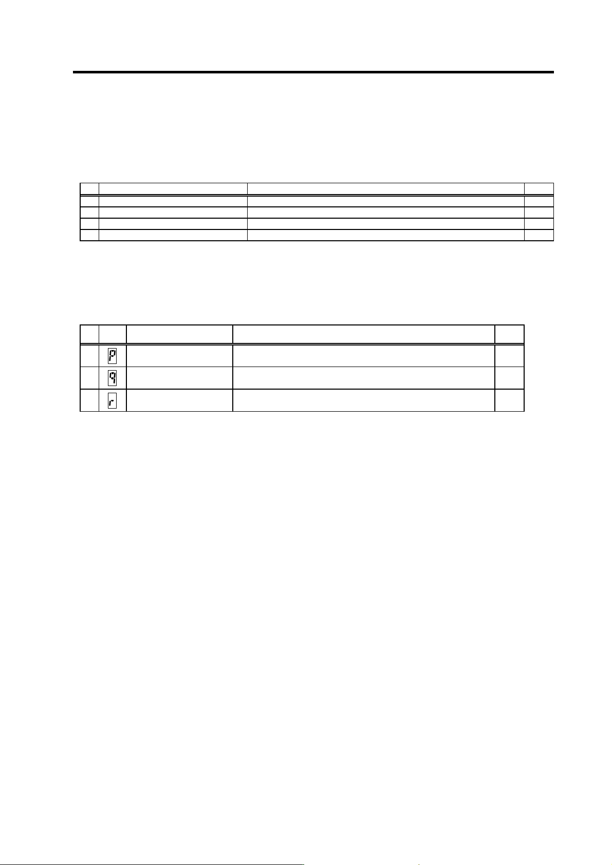
Drive unit warnings
No. Alarm name Warning details Reset
A9 Orientation feedback error warn Retrying during an orientation feedback error. *
E1 Overload warning The overload detection level is 80% or more. *
E4 Parameter error warning A parameter exceeding the setting range was set. *
E7 In emergency stop state Emergency stop was input. *
(Note 1) Spindle motor does not stop when the warning occurs.
(Note 2) When an emergency stop is input, spindle motor decelerates to a stop. However, if the machine ready complete input
signal remains ON, the operation after a stop differs according to the SP192 setting.
SP192=0 or 1: After a stop. the external contactor of CV is turned OFF after a period of time.
SP192=2 or 3: The external contactor of CV has been turned ON after a stop.
Power supply warnings
No.
LED
display
Alarm name Warning details Reset
E9
Instantaneous power failure
warning
An instantaneous power failure occurred. PR
EA
External emergency stop The external emergency stop signal was input. *
EB
Over-regeneration warning The over-regeneration level is 80% or more. *
(Note) Spindle motor does not stop when the warning occurs.
Resetting methods
* : Automatically reset once the cause of the warning is removed.
PR : Reset by setting the alarm reset signal to the general-purpose input of the spindle drive unit and turning the signal ON/OFF.
This alarm can also be reset with the AR resetting conditions.