MDS-C1-SPA Series INSTRUCTION MANUALib1500152(eng)a.pdf - 第137页
4. Spindle Adjustment 4 - 46 [4] Position loop gain and decelerati on rate adjustment at coil changeovers When using a coil changeo ver motor, the position loop gain and deceleration rate can be set for each coil. • Coil…
4. Spindle Adjustment
4 - 45
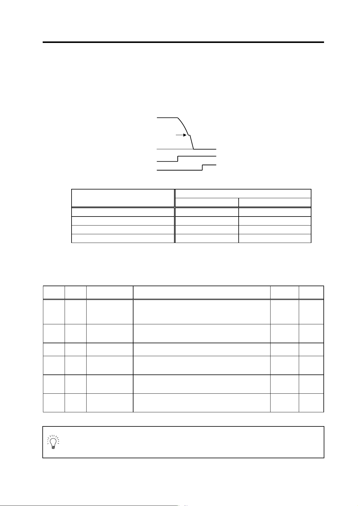
[3] Adjustment of position loop gain deceleration rate
Adjust the orientation time and vibration. Refer to the following table and adjust the parameters
according to the apparent state. When using the motor PLG and magnetic sensor, adjust the
position loop gain with SP001 (PGM). When using the spindle side detector, adjust SP002
(PGE). Adjust SP006 (CSP) after adjusting SP001 and PS002. When performing coil change
over, each coil can be adjusted individually. (Refer to the next page.)
Adjusting the orientation control
Parameter adjustment
State
SP001/SP002 SP006
The operation overshoots when stopping Decrease the setting value Decrease the setting value
The orientation time is long Increase the setting value Increase the setting value
Hunting occurs when stopping Decrease the setting value Do not change the setting value
An excessive error alarm occurs Decrease the setting value Decrease the setting value
To adjust the shortest orientation time for each gear, adjust deceleration rate for each gear by
SP107 (CSP2) to SP109 (CSP4) in the same manner. If an excessive error alarm occurs when
the gear ratio is 1:10 or more, and the state is not improved with the above adjustments, adjust
the speed clamp value (SP 005) as described later.
No. Abbr. Parameter name Details
Setting
range
Standard
SP001 PGM Magnetic sensor,
motor PLG
orientation position
loop gain
The orientation time will be shorter when the value is increased,
and the servo rigidity will increase. On the other hand, the
vibration will increase, and the machine will sway easily.
0 to1000
(0.1rad/s)
100
SP002 PGE Encoder orientation
position loop gain
The orientation time will be shorter when the value is increased,
and the servo rigidity will increase. On the other hand, the
vibration will increase, and the machine will sway easily.
0 to 1000
(0.1rad/s)
100
SP006 CSP Orientation mode
deceleration rate
As the set value is larger, the orientation time becomes shorter.
However, the machine becomes likely to overshoot.
1 to 1000 20
SP107 CSP2 Deceleration rate 2
in orientation control
mode
Set the deceleration rate in orientation mode corresponding to
the gear 001.
When this parameter is set to "0", same as SP006 (CSP).
0 to 1000 0
SP108 CSP3 Deceleration rate 3
in orientation control
mode
Set the deceleration rate in orientation mode corresponding to
the gear 010.
When this parameter is set to "0", same as SP006 (CSP).
0 to 1000 0
SP109 CSP4 Deceleration rate 4
in orientation control
mode
Set the deceleration rate in orientation mode corresponding to
the gear 011.
When this parameter is set to "0", same as SP006 (CSP).
0 to 1000 0
POINT
On machines with large spi ndle-to-motor gear ratios, it may not be possible to
achieve the desired results by adjusting the SP001, SP002, and SP006 parameters,
due to internal clamping. When clamped, the p arameter settings can be chang ed, but
control remains unch anged.
S
p
eed FB
0
ORC
ORCF
Position loop
changeover speed
4. Spindle Adjustment
4 - 46
[4] Position loop gain and deceleration rate adjustment at coil changeovers
When using a coil changeo ver motor, the position loop gain and deceleration rate can be set for
each coil.
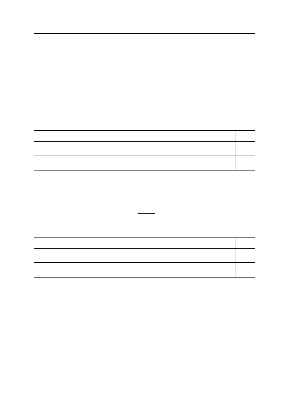
• Coil-specific orientation control position loop gain
Compensation magnification values are set for each coil by the SP119, SP120 and SP126
settings, relative to each coil's SP001 or SP002 position loop gain reference value. If a "0" is set,
the SP001 (SP002) setting is adopted.
SP119
Effective position loop gain (H-coil) = SP001 (SP002) ×
256
SP120
Effective position loop gain (L-coil) = SP001 (SP002) ×
256
No. Abbr. Parameter name Details
Setting
range
Standard
SP119 MPGH* Orientation control
position loop gain H
coil magnification
Set the compensation magnification of the orientation position
loop gain for the H coil.
0 to 2560
(1/256-fold)
0
SP120 MPGL* Orientation control
position loop gain L
coil magnification
Set the compensation magnification of the orientation position
loop gain for the L coil.
0 to 2560
(1/256-fold)
0
• Coil-specific orientation control deceleration rate
Compensation magnification values are specified for each coil by the SP121, SP122 and
SP127 settings, relative to each coil's SP006 deceleration rate reference value. If a "0" is set,
the SP006 setting is adopted.
SP121
Effective deceleration rate (H coil) = SP006 ×
256
SP122
Effective deceleration rate (L coil) = SP006 ×
256
No. Abbr. Parameter name Details
Setting
range
Standard
SP121 MPCSH* Orientation
deceleration rate H
coil magnification
Set the compensation magnification of the orientation
deceleration rate for the H coil.
0 to 2560
(1/256-fold)
0
SP122 MPCSL* Orientation
deceleration rate L
coil magnification
Set the compensation magnification of the orientation
deceleration rate for the L coil.
0 to 2560
(1/256-fold)
0
4. Spindle Adjustment
4 - 47
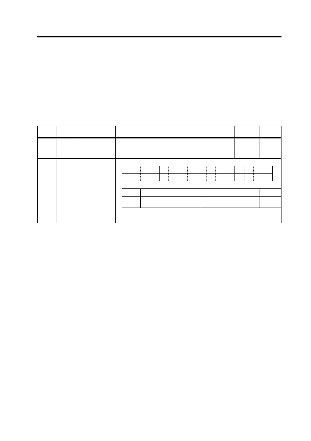
[5] Speed clamp value adjustment
The orientation control mode's position loop control changing speed is determined
automatically, based on the position loop gain, the deceleration rate, and the gear ratio, etc. A
changing speed that is too high can be limited by the orientation mode changing speed limit
value (SP005) setting. A change to the orientation motor speed clamp value 2 (SP115) occurs
at control input 4/bitC. This clamp speed can be clamped in the spindle side speed by setting
the parameter SP037(SFNC5)/bitD=1. If the gear has two or more stages and the cha nge of the
gear rate is large for the gear stage, clamping in the spindle side speed can be stopped more
stably.
No. Abbr. Parameter name Details
Setting
range
Standard
SP005 OSP Orientation mode
speed clamp value
Set the motor speed limit value to be used when the speed loop
is changed to the position loop in orientation mode.
When this parameter is set to "0", SP017 (TSP) becomes the
limit value.
0 to 32767
(r/min)
0
F EDCBA98765 4 3 2 10
dplg ospcl noplg nsno nosg psdir plgo magoenco
bit
Meaning when set to 0 Meaning when set to 1 Standard
D ospcl
Orientation speed clamp
motor speed setting
Orientation speed clamp
spindle speed setting
0
(Note) bitD is valid only for MDS-C1-SPH.
SP037 SFNC5 Spindle function 5