MDS-C1-SPA Series INSTRUCTION MANUALib1500152(eng)a.pdf - 第188页
5. Troubleshooting 5 - 17 Alarm No. 6E Memory error An error was detected in the internal memory . Investigation details Investigation results Remedies The alarm occurs each time READY is turned ON. Replace the unit. 1 C…
5. Troubleshooting
5 - 16
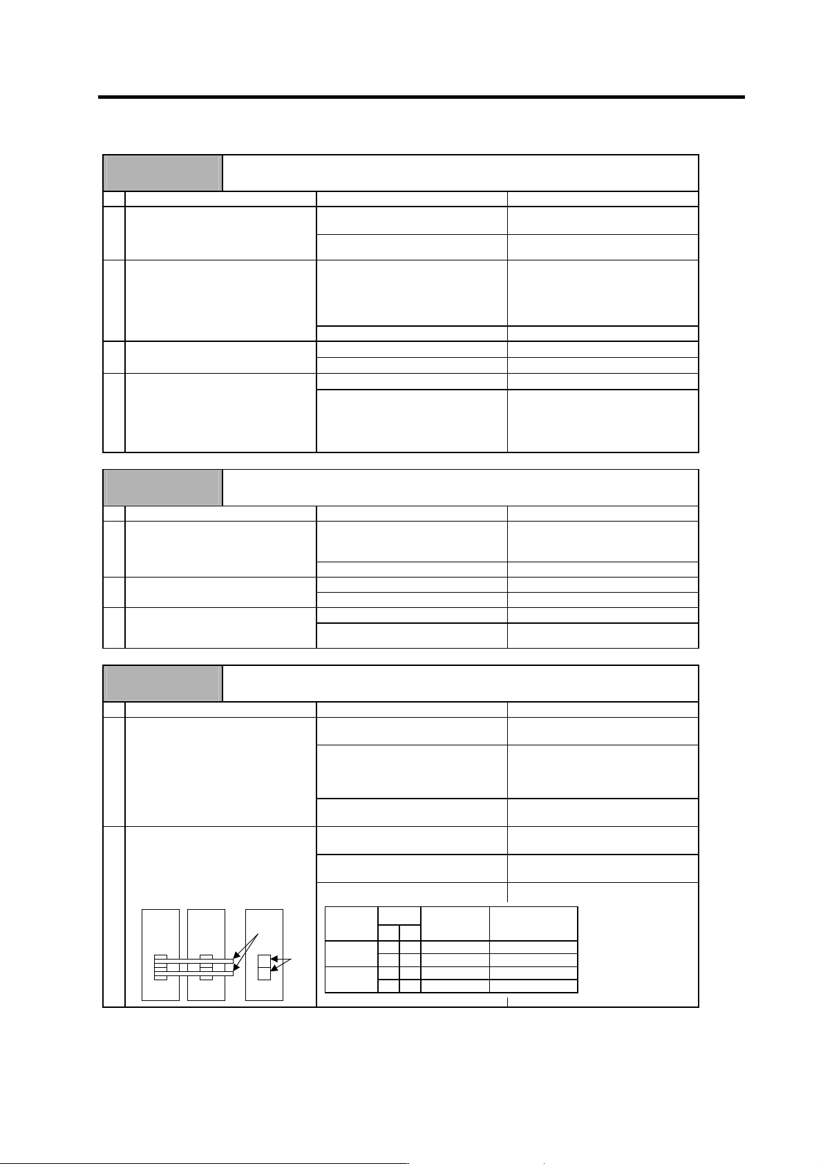
Alarm No.
69
Ground fault
The motor power cable is contacting FG (ground).
Investigation details Investigation results Remedies
100kΩ or less.
The motor or power cable may be
ground faulted.
1 Measure the insulation across the U,
V, W phase cables for all motors and
the ground. (Carry out a megger
test.)
100kΩ or more.
Investigate item 2.
Oil has come in contact. Take measures so that oil does not
come in contact. Check the motor's
cannon connector and the inside of
the terminal box, and clean as
necessary.
2 Has oil come in contact with the
motor or power cable?
Oil has not come in contact. Investigate item 3.
1MΩ or less.
Replace the motor or cable.
3 Measure the insulation again.
1MΩ or more.
Investigate item 2.
100kΩ or less.
Replace the drive unit.
4 Measure the resistance across the U,
V, W phase terminals of the
servo/spindle drive unit and the
ground.
(Do not measure the insulation, as
the unit could be damaged.)
100kΩ or more.
Replace the power supply unit.
Alarm No.
6A
External contactor melting
The external contactor's contact has melted.
Investigation details Investigation results Remedies
An alarm has occurred. Remove the cause of the alarm on
the drive side, and then carry out the
investigation details 2.
1 Check whether any alarm has
occurred on the drive unit side.
An alarm has not occurred. Investigate item 2.
The contactor has melted. Replace the contactor. 2 Check whether the contactor's
contact has melted.
The contactor has not melted. Investigate item 3.
The connection is correct. Correctly connect. 3 Check that the contactor excitation
wiring is correctly connected from the
power supply unit's MC1 terminal.
The connection is incorrect. Replace the power supply unit.
Alarm No.
6C
Main circuit error
An abnormality was detected in the main circuit capacitor's charging operation.
Investigation details Investigation results Remedies
The CHARGE lamp remains ON for
some time.
Replace the power supply unit.
The lamp turns ON instantly, but
when the alarm occurs and the
contactor turns OFF, the lamp turns
OFF immediately.
Investigate item 2.
1 Check the CHARGE lamp state when
the alarm occurs.
The lamp never turns ON. Investigate item 2.
Then replace the unit.
1) The power supply unit side is
abnormal.
Replace the power supply unit.
2) The drive unit side is abnormal. Disconnect the PN wiring, and then
check the drive unit side.
2 Disconnect the power supply unit's
PN terminal block wiring, and
measure the resistance value at 1)
and 2) shown below.
1) and 2) are both normal.
Replace the power supply unit.
Drive unit
Power supply
unit
P
N
2)
1)
Polarity
Tester
measure-
ment point
+-
Normal Abnormal
PN
Several 100Ω Short-circuit/∞Ω
1)
NP
∞Ω Several 100Ω
PN
Several 100Ω Short-circuit/∞Ω
2)
NP
∞Ω Several 100Ω
5. Troubleshooting
5 - 17
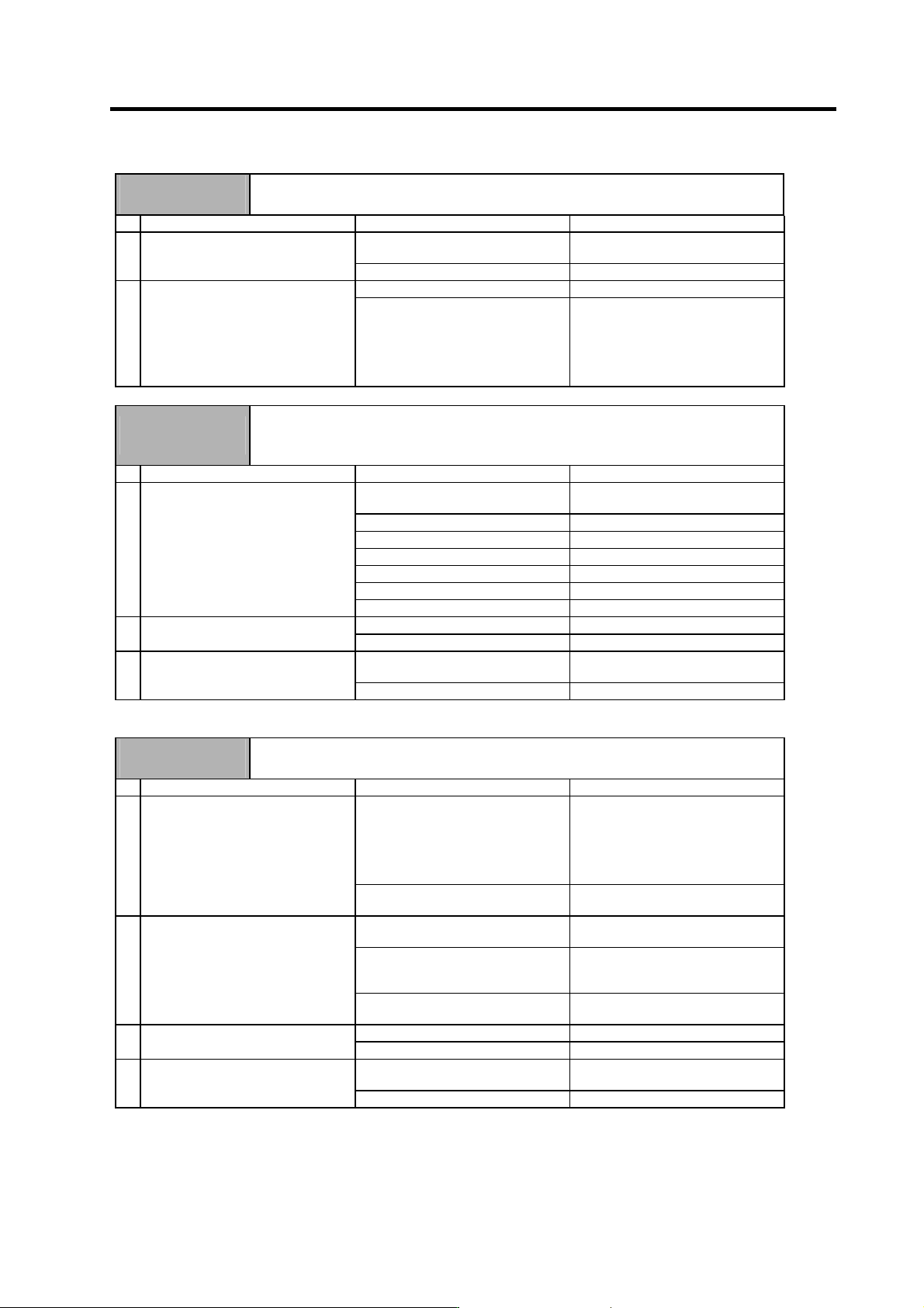
Alarm No.
6E
Memory error
An error was detected in the internal memory.
Investigation details Investigation results Remedies
The alarm occurs each time READY
is turned ON.
Replace the unit. 1 Check the repeatability.
The alarm occurs occasionally. Investigate item 2.
No abnormality is found in particular. Replace the unit. 2 Check if there is any abnormality in
the unit's ambient environment.
(Ex. Noise, grounding)
The grounding is incomplete.
An alarm will occur easily if another
device operates.
Take remedies according to the
causes of the abnormality.
Ex. Incomplete grounding:
Additionally ground.
Noise: Noise measures for
other devices.
Alarm No.
6F
Power supply error
The power supply is not connected. An error was detected in the power supply's A/D
converter.
This is detected simultaneously if another power supply alarm occurs.
Investigation details Investigation results Remedies
"F" is flickering. An A/D converter error has occurred.
Carry out the items for alarm No. 6E.
Another alarm code is flickering. Refer to the section for each alarm.
"0" is displayed. Investigate item 2.
"F" is displayed. Investigate item 2.
"8" is displayed. Refer to the section for alarm No.68.
"b", "C", "d" is displayed. Investigate item 3.
1 Check the LED display on the power
supply unit.
Something else is displayed. Refer to the section for alarm No.68.
0 or 4 is set. Investigate item 3. 2 Check the rotary switch setting.
A value other than the above is set. Correctly set the rotary switch.
There is a problem with the wiring or
shield.
Replace the cable. 3 Check the communication cable
(CN4) connected with the drive unit.
There is no problem. Replace the unit.
(Note) Alarm 6F is detected at the same time other power supply alarms occur.
Alarm No.
71
Instantaneous power failure/ external emergency stop
An instantaneous power failure occurred.
Investigation details Investigation results Remedies
The contactor has been turned OFF
externally.
Review the machine sequence.
When turning the contactor OFF with
external means, such as an
emergency stop button, this alarm
can be avoided by inputting NC
emergency stop at the same time.
1 Investigate the sequence to check
whether the contactor has been
turned OFF with an emergency stop
button, etc.
The contactor has not been turned
OFF.
Investigate item 2.
The alarm occurs each time READY
is turned ON.
Investigate item 3.
The alarm occurs at a certain
operation.
Investigate item 1.
If there is no problem, carry out
investigation item 3.
2 Check the repeatability.
The alarm occurs occasionally during
operation.
Investigate item 4.
The wiring is incorrect. Correctly connect. 3 Check whether the power input wire
and contactor are correctly wired.
There is no problem. Investigate item 4.
An instantaneous power failure or
voltage drop occurs frequently.
Correct the power facility. 4 Check the power voltage waveform
with a synchroscope.
There is no problem. Replace the unit.
5. Troubleshooting
5 - 18
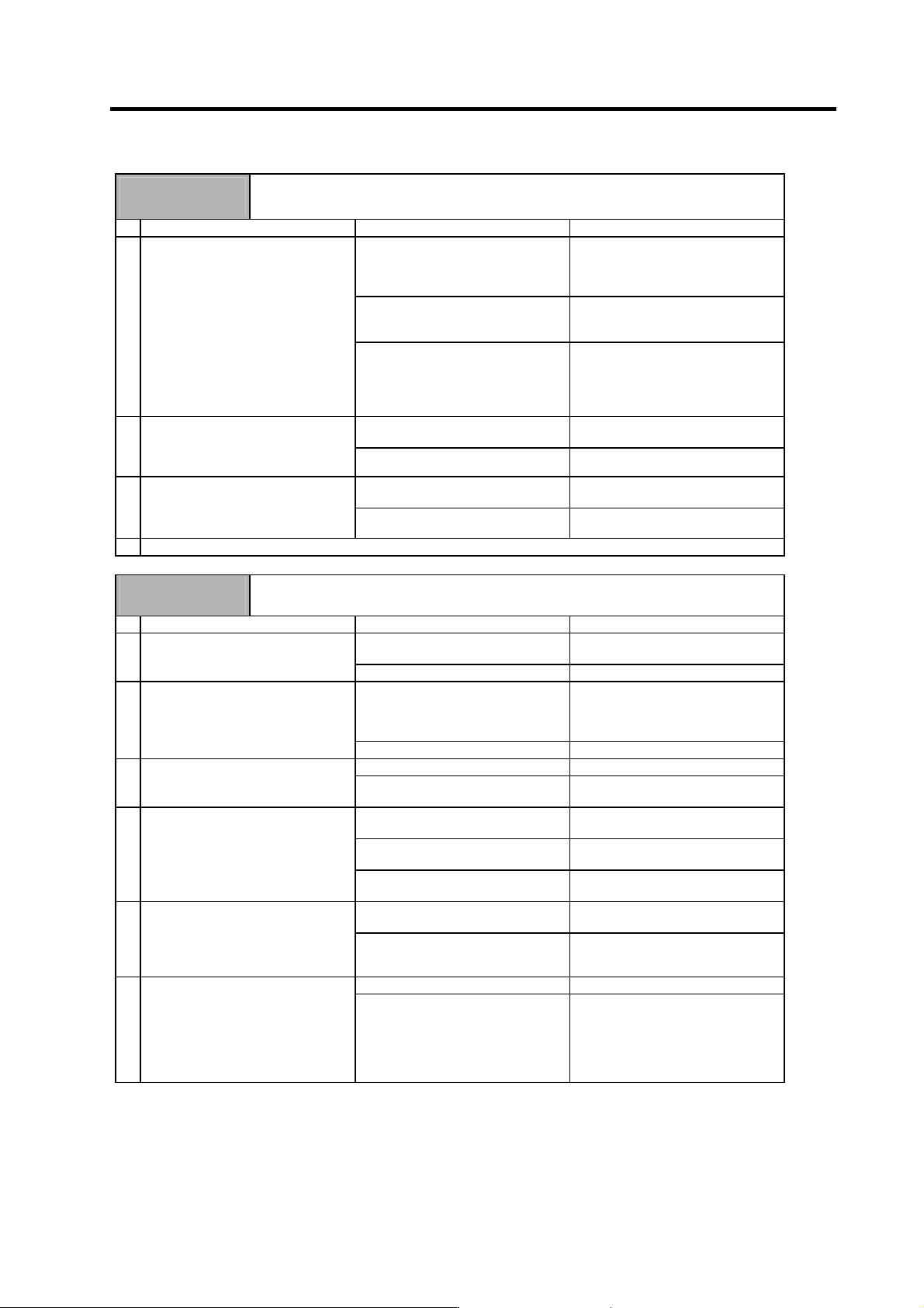
Alarm No.
73
Over-regeneration
The over-regeneration detection level exceeded 100%. The regenerative resistor is in the
overload state.
Investigation details Investigation results Remedies
The regenerative load display
increases when the power is turned
ON and the motor is not rotated.
Check whether the state is affected
by power fluctuation, grounding or
noise. If there is no problem, replace
the unit.
The regenerative load display
increases each time the motor
decelerates, and the alarm occurs.
A-CR : Investigate item 2.
C1-CV : Investigate item 4.
1 Check the alarm occurrence state
and regenerative load displayed on
the NC Monitor screen while
changing the operation mode.
The regenerative load display
increases each time the motor
decelerates, but the alarm does not
occur when the operation mode is
eased.
A-CR : Investigate item 2.
C1-CV : Ease the operation mode.
The setting is incorrect. Correctly set. (Refer to the section for
alarm No. 6D.)
2 Check whether the parameter
(regenerative resistor type) of the
drive unit controlling the power
supply unit is correct.
The setting is correct. Investigate item 3.
The regenerative resistor is
abnormal.
Replace the regenerative resistor. 3 Check the regenerative resistor's
state.
• Is oil adhered?
• Measure the resistance value.
There is no problem. Investigate item 4.
4 Check the alarm No. "75" items.
Alarm No.
75
Overvoltage
The main circuit PN bus voltage exceeded the tolerable value.
Investigation details Investigation results Remedies
The alarm occurs each time the
motor decelerates.
Investigate item 3. 1 Check the repeatability.
The alarm occurs occasionally. Investigate item 2.
Auxiliary regeneration frequency over
(E8) occurs just before the
overvoltage occurs.
Limit the occurrence of the excessive
instantaneous regeneration by not
decelerating multiple axes at the
same time.
2 Check the power supply's alarm
history.
Others. Investigate item 3.
The power capacity is insufficient. Increase the power capacity. 3 Check the power capacity.
The specified power capacity is
secured.
Investigate item 4.
The voltage drops to 170V or less
occasionally.
Increase the power capacity.
The difference of the voltage across
wires is 10V or more.
Improve the power phase balance.
4 Measure the voltage across wires.
• Is the voltage 170V or more even
when the motor is accelerating?
The difference of the voltage across
wires is less than 10V.
Investigate item 5.
The power voltage is distorted. Improve the source of the distortion.
Install an AC reactor.
5 Measure the power voltage with a
synchroscope, and check whether
there is any distortion.
• Are there any other devices
causing the power distortion?
The power voltage waveform is not
abnormal.
Investigate item 6.
No abnormality is found in particular. Replace the unit. 6 Check if there is any abnormality in
the unit's ambient environment.
(Ex. Noise, grounding)
The grounding is incomplete.
An alarm will occur easily if another
device operates.
Take remedies according to the
causes of the abnormality.
Ex. Incomplete grounding:
Additionally ground.
Noise: Noise measures for
other devices.