743844-015.pdf - 第123页
address of the channel with the smaller capacity is reached. In this mode, the system runs with one zone of dual-channel mode and one zone of single-channel mode, simultaneously , across the whole memory array . NOTE Cha…

DDR Frequency Shifting
DDR interfaces emit electromagnetic radiation which can couple to the antennas of
various radios that are integrated in the system, and cause radio frequency
interference (RFI).
The DDR Radio Frequency Interference Mitigation (DDR RFIM) feature is primarily
aimed at resolving narrowband RFI from DDR4/5 and LPDDR4/5 technologies for the
Wi-Fi* high and ultra-high bands (~5-7 GHz) .
By changing the DDR data rate, the harmonics of the clock can be shifted out of a
radio band of interest, thus mitigating RFI to that radio. This feature is working with
SAGV on, the 3
rd
SAGV point is used as RFI mitigation point.
Memory Controller (MC)
The integrated memory controller is responsible for transferring data between the
processor and the DRAM as well as the DRAM maintenance. There are two instances of
MC, one per memory slice. Each controller is capable of supporting up to four channels
of LPDDR4x and LPDDR5, two channels of DDR5 and one channel of DDR4.
The two controllers are independent and have no means of communicating with each
other, they need to be configured separately.
In a symmetric memory population, each controller only view half of the total physical
memory address space.
Both MC support only one technology in a system, DDR4 or DDR5 or LPDDR4X, or
LPDDR5. Mix of technologies in one system is not allowed.
Memory Controller Power Gate
Memory Controller Power Gating can only be done for MC0 which is connected to a
separate power domain. MC0 will be gated automatically when it is not occupied.
NOTE
MC1 cannot be gated.
System Memory Controller Organization Mode (DDR4/5 Only)
The IMC supports two memory organization modes, single-channel and dual-channel.
Depending upon how the DDR Schema and DIMM Modules are populated in each
memory channel, a number of different configurations can exist.
Single-Channel Mode
In this mode, all memory cycles are directed to a single channel. Single-Channel mode
is used when either the Channel A or Channel B DIMM connectors are populated in any
order, but not both.
Dual-Channel Mode – Intel
®
Flex Memory Technology Mode
The IMC supports Intel Flex Memory Technology Mode. Memory is divided into a
symmetric and asymmetric zone. The symmetric zone starts at the lowest address in
each channel and is contiguous until the asymmetric zone begins or until the top
5.1.3.3
5.1.4
5.1.5
5.1.6
R
Intel
®
Core
™
, Xeon
™
6300 And Xeon
™
E 2400 Processors—Memory
13
th
Generation Intel
®
Core
™
, Intel
®
Core
™
14
th
Generation, Intel
®
Core
™
Processor (Series 1) and (Series 2), Intel
®
Xeon
™
E
2400 Processor and Intel
®
Xeon
™
6300 Processor
Datasheet, Volume 1 of 2 May 2025
122 Doc. No.: 743844, Rev.: 015
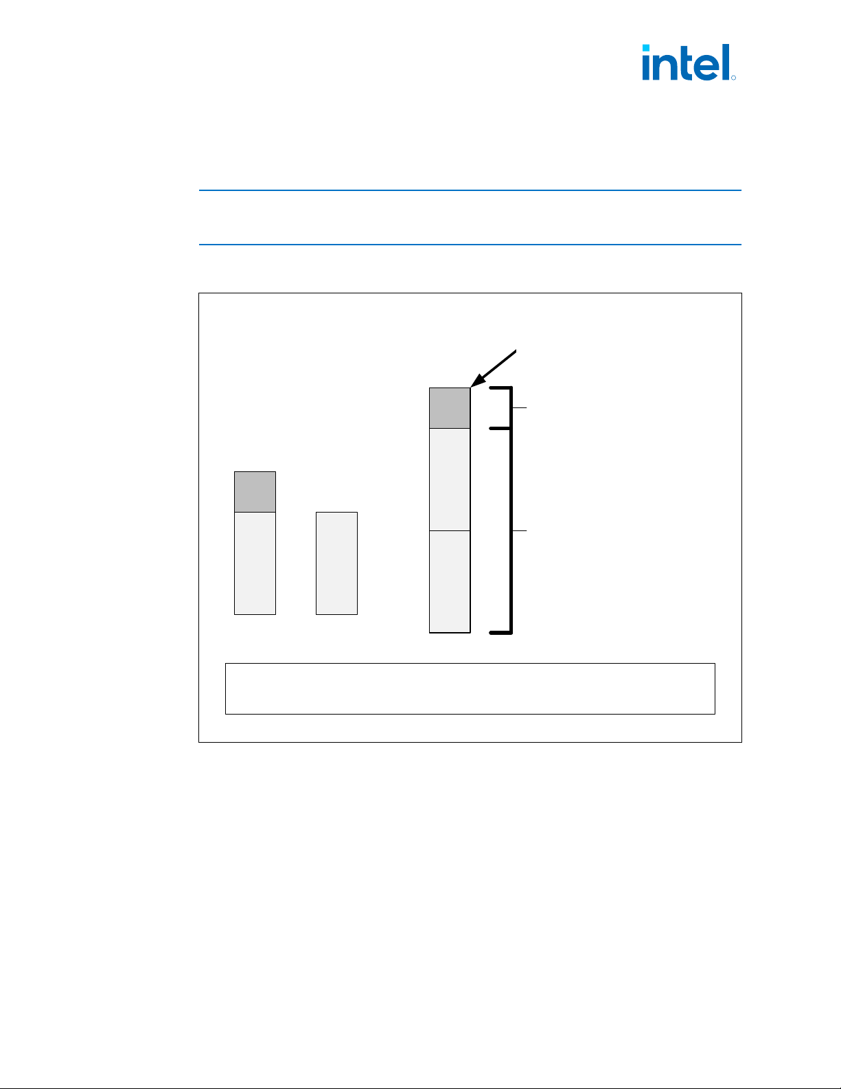
address of the channel with the smaller capacity is reached. In this mode, the system
runs with one zone of dual-channel mode and one zone of single-channel mode,
simultaneously, across the whole memory array.
NOTE
Channels A and B can be mapped for physical channel 0 and 1 respectively or vice
versa; however, channel A size should be greater or equal to channel B size.
Figure 19. Intel
®
DDR4/5 Flex Memory Technology Operations
MC BMC A
B B
C
B
B
C
Non interleaved
access
Dual channel
interleaved access
TOM
MC A and MC B can be configured to be physical channels 0 or 1
B – The largest physical memory amount of the smaller size memory module
C – The remaining physical memory amount of the larger size memory module
Dual-Channel Symmetric Mode (Interleaved Mode)
Dual-Channel Symmetric mode, also known as interleaved mode, provides maximum
performance on real world applications. Addresses are ping-ponged between the
channels after each cache line (64-byte boundary). If there are two requests, and the
second request is to an address on the opposite channel from the first, that request
can be sent before data from the first request has returned. If two consecutive cache
lines are requested, both may be retrieved simultaneously, since they are ensured to
be on opposite channels. Use Dual-Channel Symmetric mode when both Channel A
and Channel B DIMM connectors are populated in any order, with the total amount of
memory in each channel being the same.
R
Memory—Intel
®
Core
™
, Xeon
™
6300 And Xeon
™
E 2400 Processors
13
th
Generation Intel
®
Core
™
, Intel
®
Core
™
14
th
Generation, Intel
®
Core
™
Processor (Series 1) and (Series 2), Intel
®
Xeon
™
E
2400 Processor and Intel
®
Xeon
™
6300 Processor
May 2025 Datasheet, Volume 1 of 2
Doc. No.: 743844, Rev.: 015 123

When both channels are populated with the same memory capacity and the boundary
between the dual channel zone and the single channel zone is the top of memory, IMC
operates completely in Dual-Channel Symmetric mode.
NOTES
• The DRAM device technology and width may vary from one channel to another.
• Different memory size between channels are relevant to DDR4 and DDR5 only.
System Memory Frequency
In all modes, the frequency of system memory is the lowest frequency and latency of
all memory modules placed in the system, as determined through the SPD registers
on the memory modules. The system memory controller supports a single DIMM
connector per channel. If DIMMs with different latency are populated across the
channels, the BIOS will use the slower of the two latencies for both channels. For
Dual-Channel modes, both channels should have a DIMM connector populated. For
Single-Channel mode, only a single channel can have a DIMM connector populated.
Technology Enhancements of Intel
®
FMA
The following sections describe the Just-in-Time Scheduling, Command Overlap, and
Out-of-Order Scheduling Intel
®
Fast Memory Access (Intel
®
FMA) technology
enhancements.
Just-in-Time Command Scheduling
The memory controller has an advanced command scheduler where all pending
requests are examined simultaneously to determine the most efficient request to be
issued next. The most efficient request is picked from all pending requests and issued
to system memory Just-in-Time to make optimal use of Command Overlapping. Thus,
instead of having all memory access requests go individually through an arbitration
mechanism forcing requests to be executed one at a time, they can be started without
interfering with the current request allowing for concurrent issuing of requests. This
allows for optimized bandwidth and reduced latency while maintaining appropriate
command spacing to meet system memory protocol.
Command Overlap
Command Overlap allows the insertion of the DRAM commands between the Activate,
Pre-charge, and Read/Write commands normally used, as long as the inserted
commands do not affect the currently executing command. Multiple commands can be
issued in an overlapping manner, increasing the efficiency of system memory protocol.
Out-of-Order Scheduling
While leveraging the Just-in-Time Scheduling and Command Overlap enhancements,
the IMC continuously monitors pending requests to system memory for the best use of
bandwidth and reduction of latency. If there are multiple requests to the same open
page, these requests would be launched in a back to back manner to make optimum
use of the open memory page. This ability to reorder requests on the fly allows the
IMC to further reduce latency and increase bandwidth efficiency.
5.1.7
5.1.8
R
Intel
®
Core
™
, Xeon
™
6300 And Xeon
™
E 2400 Processors—Memory
13
th
Generation Intel
®
Core
™
, Intel
®
Core
™
14
th
Generation, Intel
®
Core
™
Processor (Series 1) and (Series 2), Intel
®
Xeon
™
E
2400 Processor and Intel
®
Xeon
™
6300 Processor
Datasheet, Volume 1 of 2 May 2025
124 Doc. No.: 743844, Rev.: 015